Photomultiplier and sensor module

a sensor module and photomultiplier technology, applied in the direction of multiplier dynodes, multiplier electrode arrangements, electric discharge tubes, etc., can solve the problems of glass containers that cannot provide the conventional photomultiplier has a possibility of failing to maintain sufficient durability and high reliability, so as to improve the anti-vibration performance of the photomultiplier

Active Publication Date: 2015-07-02
HAMAMATSU PHOTONICS KK
View PDF7 Cites 1 Cited by
  • Summary
  • Abstract
  • Description
  • Claims
  • Application Information

AI Technical Summary

Benefits of technology

[0010]The structure for fixing the installation position of the electron multiplier unit in the sealed container is realized by a fixing member forming a part of the sealed container. Specifically, the fixing member has an aperture for defining an installation position of the focusing electrode, an inside end defining the aperture, and an outside end surrounding the inside end. Furthermore, the outside end is grasped by the first ceramic side tube and the second ceramic side tube whereby the fixing member is fixed to the sealed container. On the other hand, the inside end of the fixing member located in the sealed container is fixed to the focusing electrode. This configuration fixes the installation position of the electron multiplier unit relative to the sealed container, thereby to achieve drastic improvement in anti-vibration performance of the photomultiplier.

Problems solved by technology

For this reason, when we assume that the photomultiplier is used under severe environments, e.g., in underground resource exploration, the conventional photomultiplier had a possibility of failing to maintain sufficient durability and high reliability.
For example, when the photomultiplier is assumed to be used in a high-temperature, high-pressure environment, the glass container can possibly fail to provide sufficient durability.
In addition, the position of the electron multiplier unit relative to the glass container varies with intense vibration in the structure where the electron multiplier unit is held at the predetermined position in the glass container, and thus the reliability can also possibly degrade.
Particularly, in the ordinary configuration wherein the glass container and a part of the electron multiplier unit are held by springs on the inner wall of the glass container, if unwanted gas is produced in the glass container because of friction by vibration, the photomultiplier will inevitably undergo degradation of reliability (reduction in measurement sensitivity, malfunction, and so on).

Method used


Image

  • Photomultiplier and sensor module
  • Photomultiplier and sensor module
  • Photomultiplier and sensor module

Examples


Embodiment Construction

[0034]Various embodiments of the photomultiplier and sensor module according to the present invention will be described below in detail with reference to the accompanying drawings. In the description of the drawings the same portions and the same elements will be denoted by the same reference signs, without redundant description.

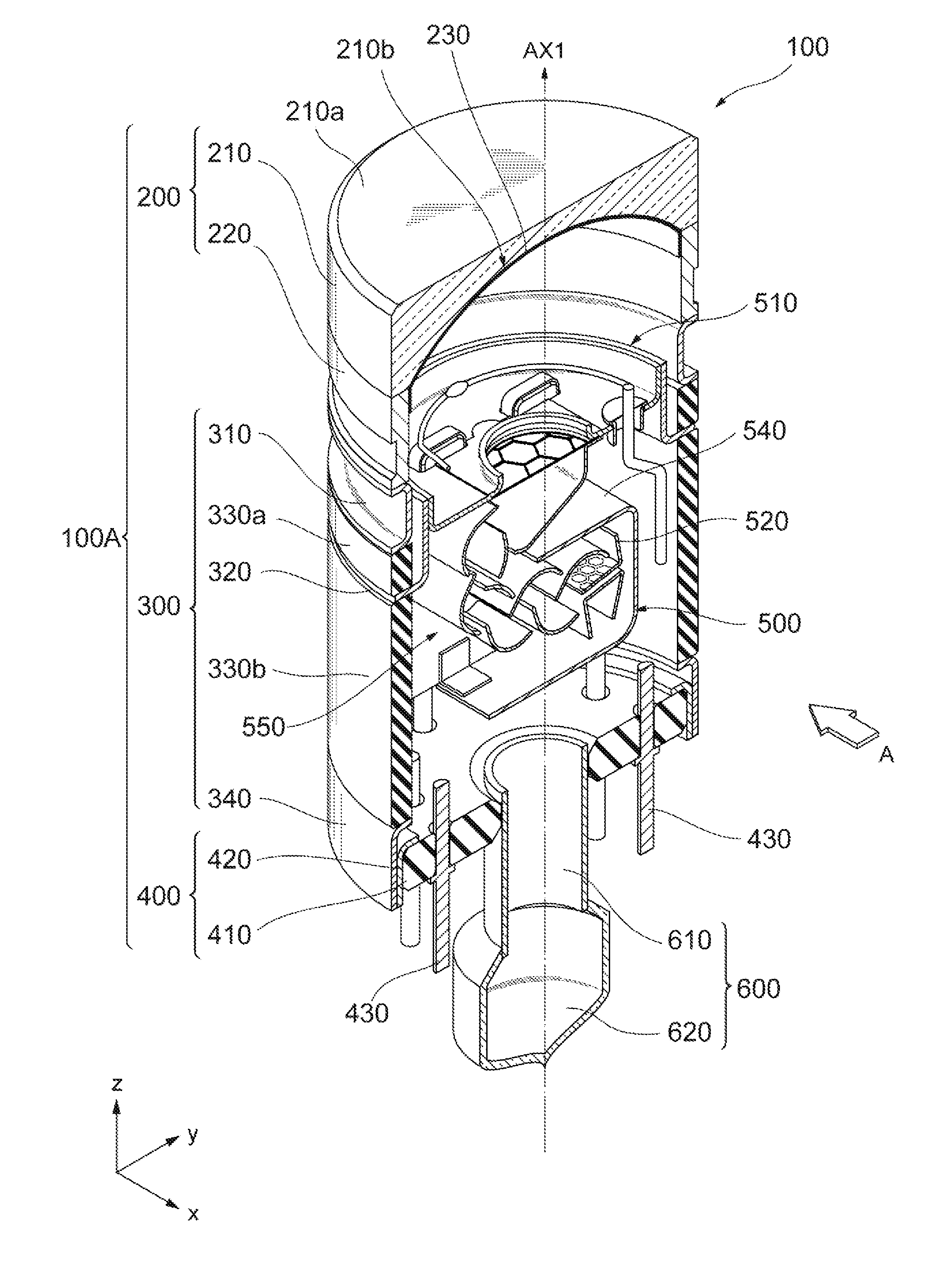
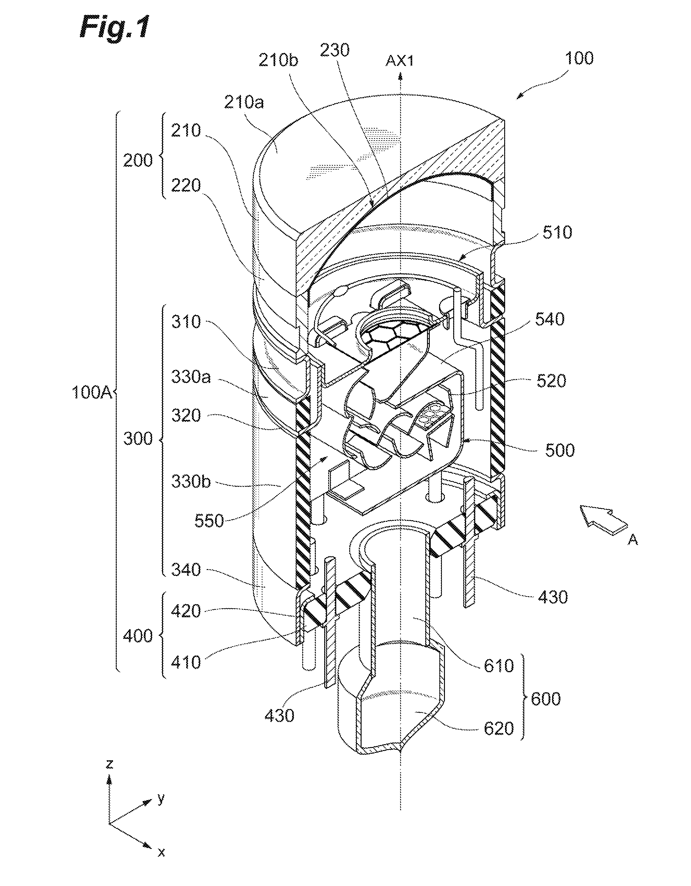
[0035]FIG. 1 is a partly broken view showing an internal structure of a photomultiplier according to an embodiment of the present invention, and FIG. 2 a drawing showing a cross-sectional structure of the photomultiplier according to the embodiment of the present invention, which is a view from a direction indicated by an arrow A in FIG. 1.

[0036]As shown in FIG. 1, the photomultiplier 100 has a sealed container 100A to a bottom part of which an exhaust tube 600 (a glass part of which is sealed after evacuation) for evacuating the interior is attached, and also has a photocathode 230 and an electron multiplier unit 500 provided in this sealed container 100A.

[...


PUM


Abstract

A photomultiplier according to an embodiment of the present invention has a sealed container the interior of which is maintained in a vacuum state, and an electron multiplier unit housed in the sealed container, and the sealed container is partly constructed of ceramic side tubes, on the assumption that the photomultiplier is used under high-temperature, high-pressure environments. The photomultiplier further has a structure for fixing an installation position of the electron multiplier unit relative to the sealed container, for improvement in anti-vibration performance.

Description

BACKGROUND OF THE INVENTION[0001]1. Field of the Invention[0002]The present invention relates to a photomultiplier and a sensor module including the same.[0003]2. Related Background Art[0004]Japanese Patent No. 4640881 (Japanese Patent Application Laid-Open Publication No. 2002-42719) discloses a photomultiplier having a glass container the interior of which is maintained in a vacuum state, and an electron multiplier unit housed in the glass container. In this photomultiplier, the electron multiplier unit is held at a predetermined position in the glass container in a state in which it is supported by lead pins extending from a bottom (stem) of the glass container.SUMMARY OF THE INVENTION[0005]The Inventors examined the conventional photomultiplier and found the problem as described below. Specifically, in the conventional photomultiplier the relative position of the electron multiplier unit to the glass container is maintained by only the lead pins extending from stem pins. For thi...

Claims


Application Information

Patent Timeline
Patent Type & Authority Applications(United States)
IPC IPC(8): H01J43/28H01J43/10
CPCH01J43/10H01J43/28
Inventor ISHIZU, TOMOHIROFUJITA, TETSUYASUZUKI, TAKAHIRO
Owner HAMAMATSU PHOTONICS KK
Why Eureka
Try Eureka