Eureka AIR delivers breakthrough ideas for toughest innovation challenges, trusted by R&D personnel around the world.

System for recirculating engine exhaust gas

a technology of exhaust gas and system, which is applied in the direction of machines/engines, mechanical equipment, output power, etc., can solve the problems of degrading the overall performance of the turbine and the engine system, degrading the exhaust gas recirculation system, and increasing the back pressure, so as to reduce manufacturing costs, simplify the structure of the system, and improve the output of the engine

Active Publication Date: 2015-07-02
DOOSAN INFRACORE CO LTD
View PDF1 Cites 2 Cited by
  • Summary
  • Abstract
  • Description
  • Claims
  • Application Information

AI Technical Summary

Benefits of technology

The system for recirculating engine exhaust gas described in this patent can reduce manufacturing costs by simplifying the structure of the system. It can also increase the amount of intake air, improving engine output and fuel efficiency.

Problems solved by technology

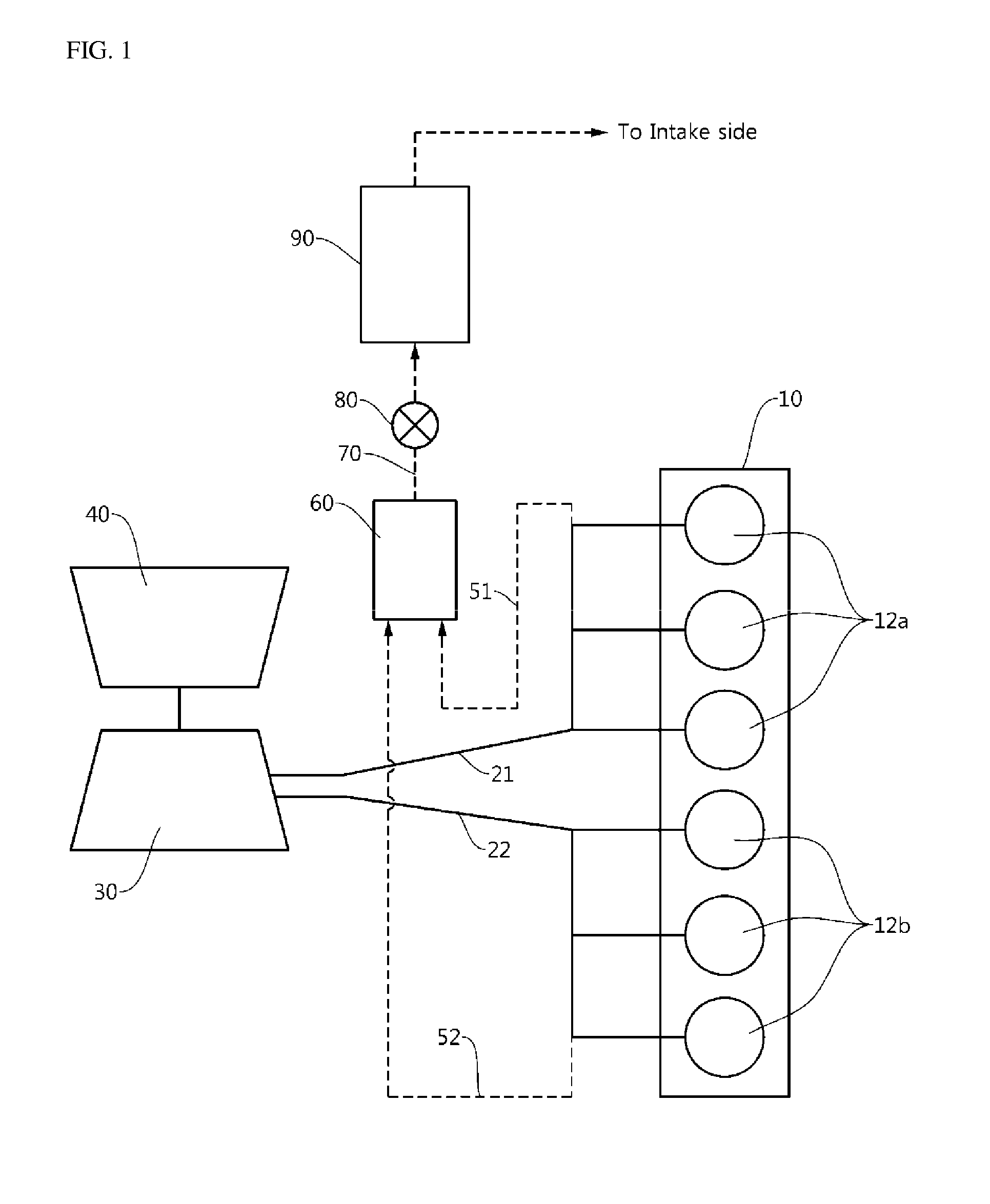
There is a problem in that the aforementioned back pressure interference action degrades performance of the exhaust gas recirculation system.
In the exhaust gas recirculation system, when recirculating gas is obtained from only one exhaust manifold, imbalance in pressure and flow rate between two lines leading to the turbine is caused, which degrades overall performance of the turbine and the engine system.
However, in a case in which a phenomenon that exhaust pressures waves are exchanged through both the exhaust manifolds is not effectively inhibited, there is a problem in that back pressure is increased such that performance of the exhaust gas recirculation system deteriorates.
However, in this example, since additional valves need to be installed and designed, there is a problem in that costs are increased.
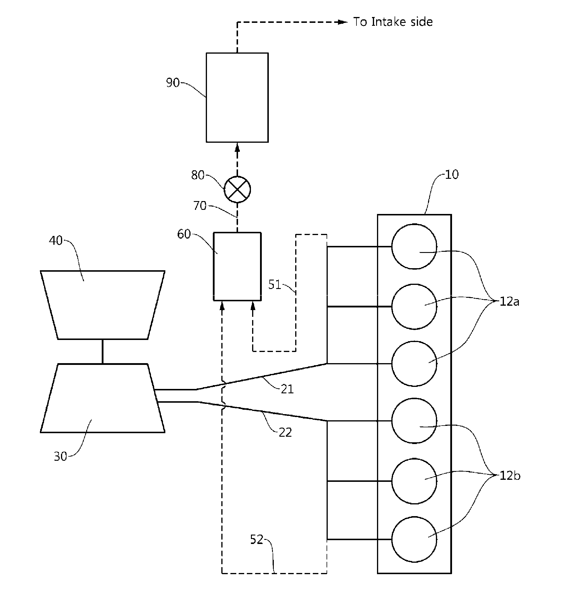
However, the exhaust gas recirculation system in the related art illustrated in FIG. 1 has a complicated structure, and as a result, there is a problem in that manufacturing costs are increased.
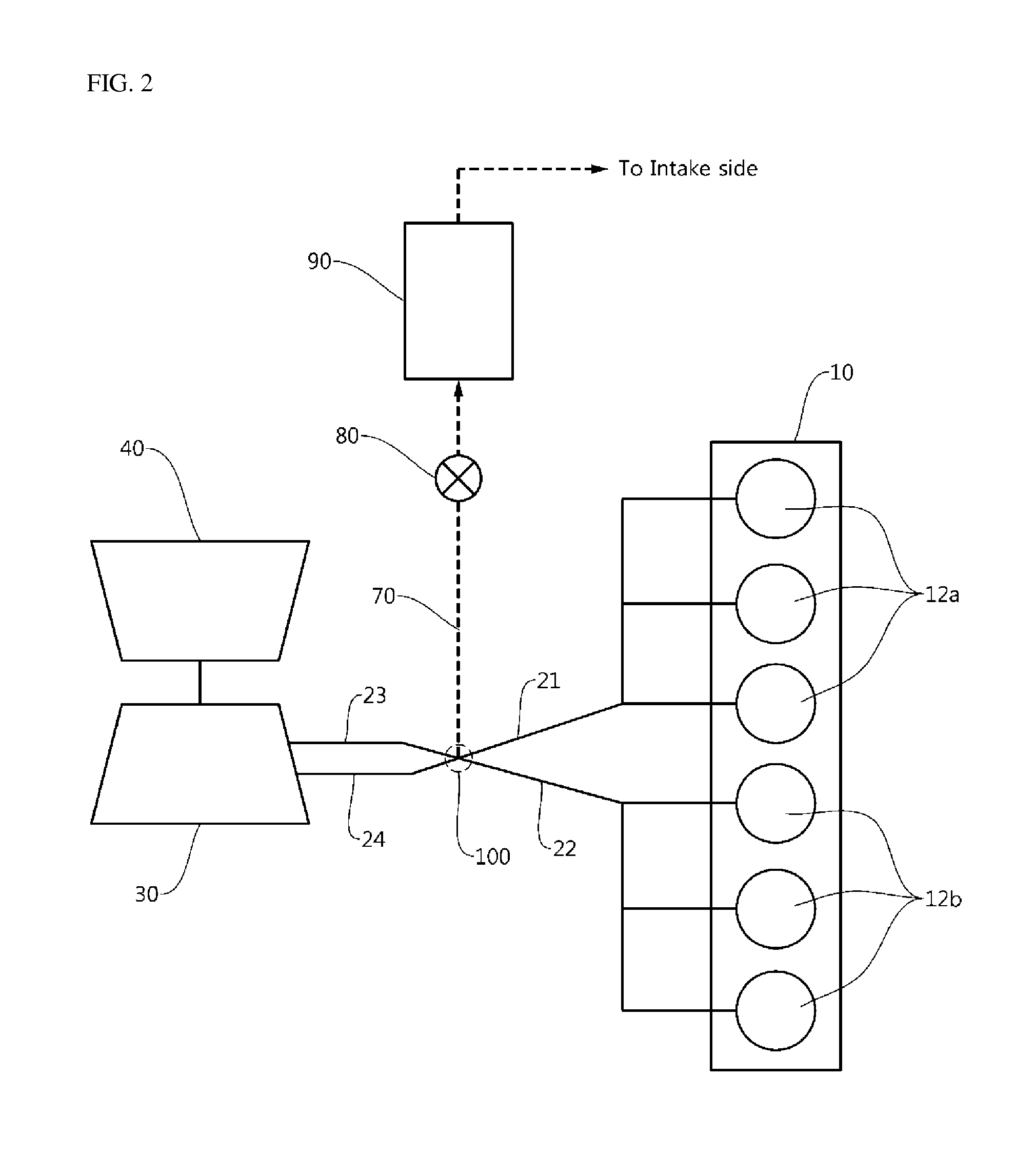
Therefore, a technical problem to be achieved in some embodiments of the present disclosure is to provide a system for recirculating engine exhaust gas which may have a simplified structure.

Method used


Image

  • System for recirculating engine exhaust gas
  • System for recirculating engine exhaust gas
  • System for recirculating engine exhaust gas

Examples


Embodiment Construction

[0051]Advantages and features of the present disclosure and methods of achieving the advantages and features will be clear with reference to an exemplary embodiment described in detail below together with the accompanying drawings.

[0052]Like reference numerals indicate like elements throughout the specification, constituent elements identical to constitute elements in the related art will be indicated by the same reference numerals, and duplicated descriptions thereof will be omitted.

[0053]Meanwhile, the terms used in the description are defined considering the functions of the present disclosure and may vary depending on the intention or usual practice of a manufacturer. Therefore, the definitions should be made based on the entire contents of the present specification.

[0054]Hereinafter, a system for recirculating engine exhaust gas according to an exemplary embodiment of the present disclosure will be described with reference to FIG. 2.

[0055]The attached FIG. 2 is a view for expla...


PUM


Abstract

The present disclosure relates to a system for recirculating engine exhaust gas, and more particularly, to a system for recirculating engine exhaust gas, which mixes a part of exhaust gas discharged from an engine with air for combustion, and recirculates the mixture, thereby inhibiting nitrogen oxide (NOx) from being generated. Therefore, a technical problem to be achieved in the present disclosure is to provide a system for recirculating engine exhaust gas which may have a simplified structure. In addition, another object of the present disclosure is to provide a system for recirculating engine exhaust gas, which improves output of an engine by increasing an amount of intake air, and further improves fuel efficiency.

Description

CROSS-REFERENCE TO RELATED APPLICATION[0001]This Application is a Section 371 National Stage Application of International Application No. PCT / KR2013 / 002818, filed Apr. 4, 2013 and published, not in English, as WO 2013 / 151356 on Oct. 10, 2013.FIELD OF THE DISCLOSURE[0002]The present disclosure relates to a system for recirculating engine exhaust gas, and more particularly, to a system for recirculating engine exhaust gas, which mixes a part of exhaust gas discharged from an engine with air for combustion, and recirculates the mixture, thereby inhibiting nitrogen oxide (NOx) from being generated.BACKGROUND OF THE DISCLOSURE[0003]In general, an engine uses gasoline or diesel as fuel, nitrogen oxide (NOx) is included in exhaust gas and discharged when fuel is combusted and exhaust gas is discharged.[0004]Because nitrogen oxide causes environmental pollution, a technology for inhibiting the nitrogen oxide from being generated is being developed, and as the technology, there is an exhaust...

Claims


Application Information

Patent Timeline
Patent Type & Authority Applications(United States)
IPC IPC(8): F02M25/07
CPCF02M25/0715F02M25/0726F01N13/107F02B37/025F02M26/05F02M26/14F02M26/22F02M26/23F02M26/42Y02T10/12F02D21/08F02D13/0276
Inventor WANG, TAEJOONGLEE, DONGIN
Owner DOOSAN INFRACORE CO LTD
Why Eureka
Eureka Blog
Learn More