Apparatus and method for controlling a lubriation unit using flow rate feedback

a technology of flow rate feedback and actuator, which is applied in the direction of mechanical equipment, machines/engines, positive displacement liquid engines, etc., can solve the problems of insufficient suction to fill the pump cylinder, insufficient lubricant being dispensed to the lubrication points, and the aggregate amount of lubricant dispensed and the flow rate cannot be determined

Active Publication Date: 2015-06-25
LINCOLN INDUSTRIES CORP
View PDF9 Cites 15 Cited by
  • Summary
  • Abstract
  • Description
  • Claims
  • Application Information

AI Technical Summary

Problems solved by technology

If lubricant does not fill a total volume of the pump cylinder during each stroke, the aggregate amount of lubricant dispensed and the flow rate cannot be determined absent additional equipment.
), the lubricant becomes more viscous and frequently results in an inability to draw sufficient suction to fill the pump cylinder.
In lube systems where pump operation is controlled by determining the amount of lubricant dispensed or the lubricant flow rate from pump cylinder volume, not filling the cylinder may result in insufficient lubricant being dispensed to the lubrication points.

Method used


Image

  • Apparatus and method for controlling a lubriation unit using flow rate feedback
  • Apparatus and method for controlling a lubriation unit using flow rate feedback
  • Apparatus and method for controlling a lubriation unit using flow rate feedback

Examples


Embodiment Construction

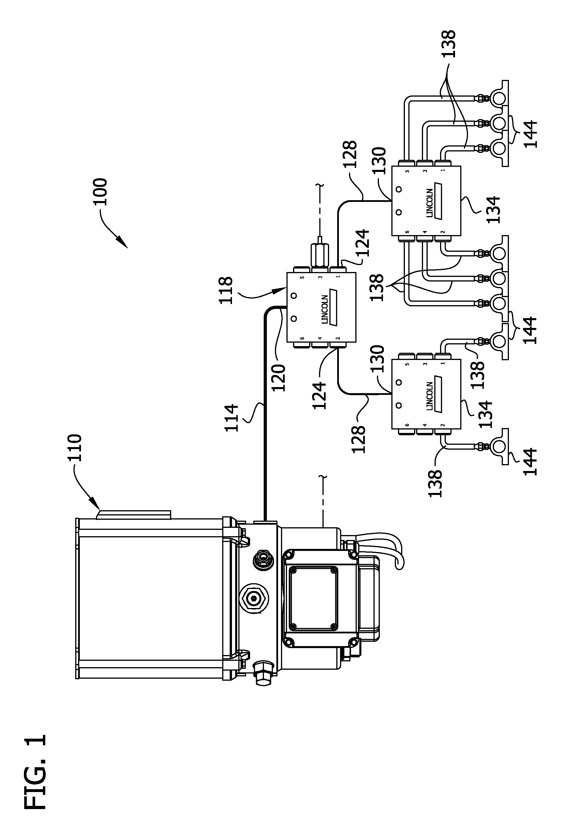
[0015]FIG. 1 illustrates a conventional Quicklub® system, generally designated 100, comprising a pump unit 110 that operates to pump lubricant through a lube supply line 114 to a master divider valve, generally designated by 118, having an inlet 120 and multiple outlets 124 connected via lines 128 to the inlets 130 of additional (slave) divider valves, generally designated by 134. The divider valves 134 are connected via lines 138 to bearings 144 or other points of lubrication. The number of divider valves 134 used will vary depending on the number of lubrication points to be serviced.

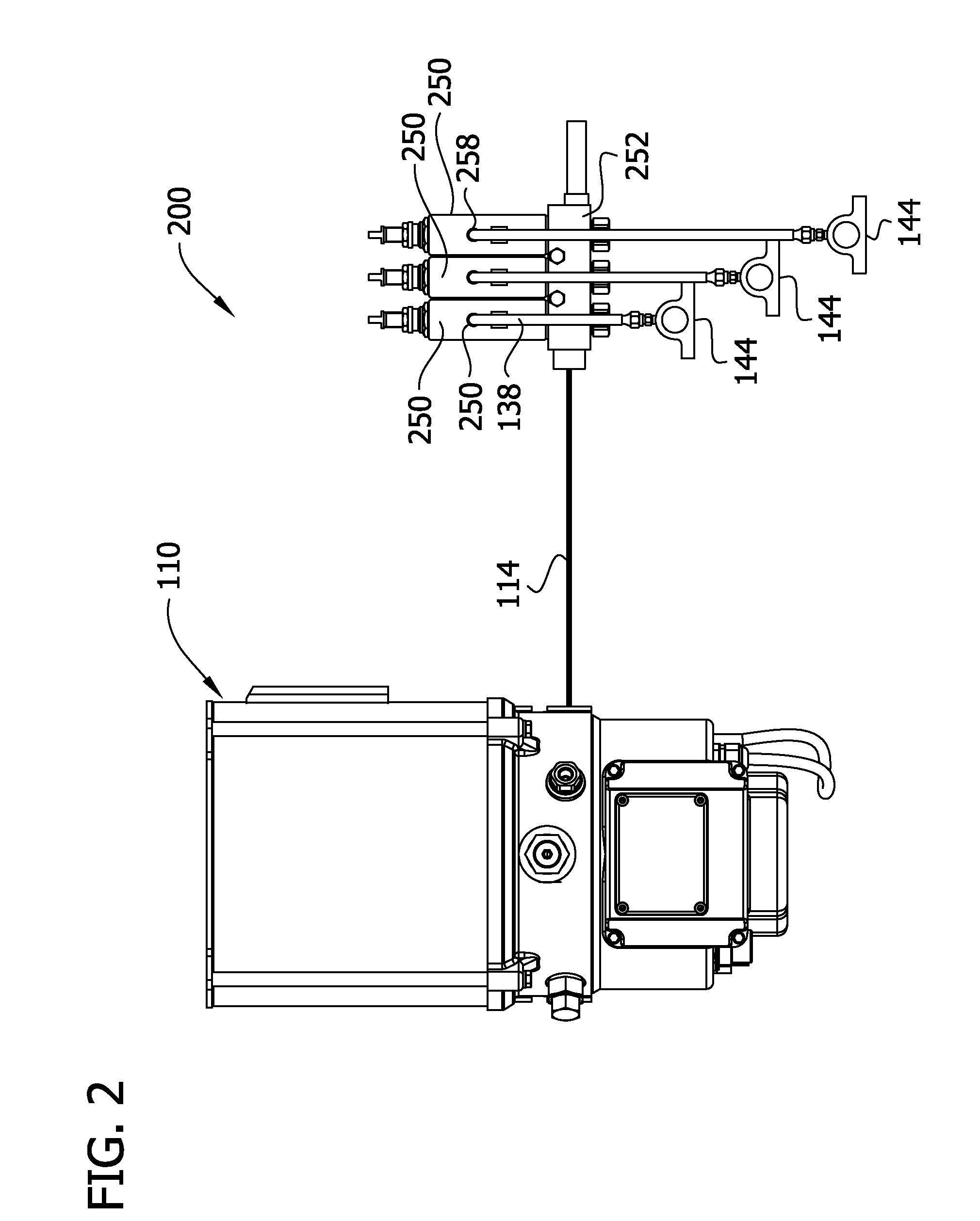
[0016]FIG. 2 illustrates a conventional Centro-Matic® system, generally designated 200, comprising a pump unit 110 that operates to pump lubricant through a lube supply line 114 to a plurality of injectors 250, each of which has an inlet communicating with the lube supply line 114 via passages in a manifold 252 and an outlet 158 connected via a line 138 to a bearing 144 or other point of lubrication.

[0...


PUM


Abstract

A lubrication unit for delivering lubricant in a system and a method for controlling the unit. The lubrication unit includes a reservoir, a motor, and a pump. The lubrication unit has a flow rate sensor mounted downstream from the pump for measuring a flow rate of lubricant. The lubrication unit includes a control unit operatively connected to the flow rate sensor and the motor for controlling operation of the motor. The control unit includes an input selector for selecting at least one characteristic selected from a group consisting of a volume and a flow rate of lubricant pumped by the pump. The control unit adjusts motor speed to obtain the selected characteristic.

Description

FIELD OF THE INVENTION[0001]The present invention generally relates to apparatus and method for supplying lubricant, and more particularly to an apparatus and method of controlling lubrication units using flow rate feedback.BACKGROUND OF THE INVENTION[0002]This invention has particular application to automatic lubrication systems for supplying lubricant to multiple points of lubrication at predetermined intervals and / or in predetermined amounts. Lincoln Industrial sells such automated systems under the Quicklub®, Centro-Matic®, and Helios® trademarks. The Quicklub® system includes a reservoir for holding a supply of lubricant, a stirrer for stirring the lubricant, and an electric or pneumatic pump for pumping lubricant from the reservoir to one or more progressive metering (divider) valves each of which operates to dispense lubricant to multiple points of lubrication. Reference may be made to U.S. Pat. No. 6,244,387, incorporated herein by reference, for further details regarding an...

Claims


Application Information

Patent Timeline
Patent Type & Authority Applications(United States)
IPC IPC(8): F16N29/02F16N13/06
CPCF16N29/02F16N2013/063F16N13/06F16N2250/00
Inventor CONLEY, PAUL G.ALEKSEYEV, VICKTOR
Owner LINCOLN INDUSTRIES CORP
Why Eureka
Try Eureka