
System and method for ensuring cutting accuracy in a mailpiece wrapper

a technology of mailpiece and cutting accuracy, applied in the field of mailpiece fabrication systems, can solve problems such as difficulties, adverse impact on throughput, and difficulty, and achieve the effects of avoiding re-cutting, avoiding re-cutting, and avoiding re-cutting

Active Publication Date: 2015-06-25
DMT SOLUTIONS GLOBAL CORP
View PDF27 Cites 9 Cited by
  • Summary
  • Abstract
  • Description
  • Claims
  • Application Information

AI Technical Summary

Benefits of technology

The patent describes an improved system and method for making finished envelopes by assembling content materials and wrapping materials. The system uses a continuous web of printed substrate with cut quality marks for individual envelopes. An imaging device captures image data of the cut quality marks and a controller compares it with an expected dimension and produces an error signal if there is a deviation. The system also includes an outsort station to remove defective envelopes. The cut quality marks are positioned on the cut lines of the continuous web and can be on the inner or outer surface of the assembled envelope. The system ensures consistent quality and efficiency in the production of finished envelopes.

Problems solved by technology

While a variety of mailpiece fabrication errors can occur to adversely impact throughput, one of the more frequent sources originates from the handling apparatus of the wrapping module.
More specifically, difficulties arise when placing the content material into the open end of the tube-shaped wrap such that the content material is placed into and remains at the proper location relative to adhesive deposited along the peripheral edges of the mailpiece.
A further difficulty can arise if the cutting mechanism for separating the individual envelopes gets out of phase with the continuous web of envelope material.

Method used


Image

  • System and method for ensuring cutting accuracy in a  mailpiece wrapper
  • System and method for ensuring cutting accuracy in a  mailpiece wrapper
  • System and method for ensuring cutting accuracy in a  mailpiece wrapper

Examples


Embodiment Construction

[0026]While the invention is described in the context of a paper-based wrapping system, i.e., a system which is fed by a paper web, for creating finished mailpieces, the invention is equally applicable to other mailpiece fabrication systems wherein adhesive is applied to a substrate material used to produce an envelope. Consequently, the detailed description and illustrations are merely indicative of an embodiment of the invention, and, accordingly, the invention should be broadly interpreted in accordance with the appended claims.

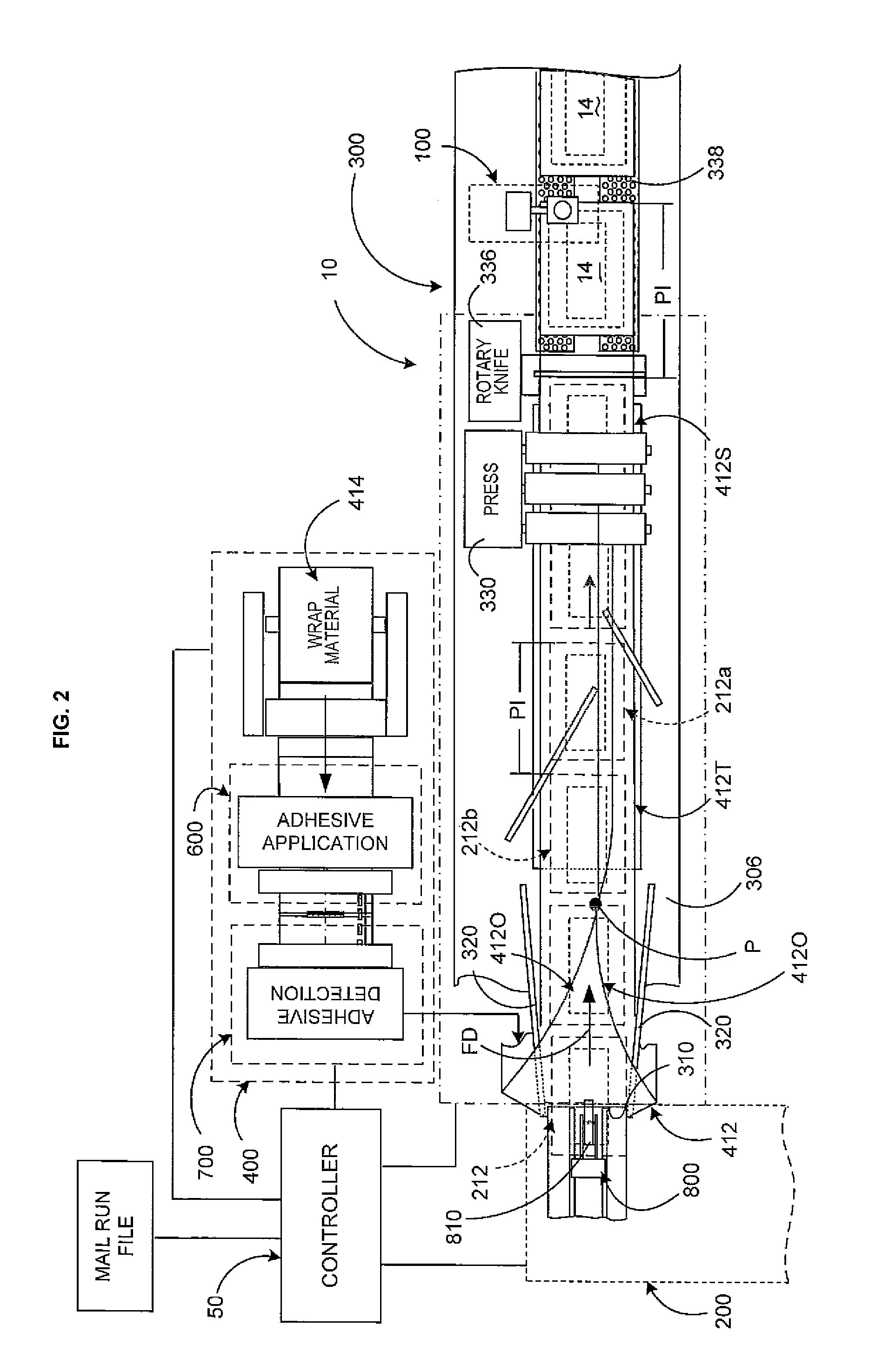
[0027]Before discussing some of the more relevant details of the system and method of the present invention, a brief overview of a mailpiece fabrication system will be provided. FIGS. 1 and 2 depict a schematic block diagram of a mailpiece fabrication system 10 according to the present invention wherein: (i) a supply of content material 212 is produced by a variety of upstream content fabrication modules 200, (ii) a wrapping system 300 receives a supply of...


PUM

PropertyMeasurementUnit
temperatureaaaaaaaaaa
wavelengthaaaaaaaaaa

Abstract

An improved mailpiece fabrication system assembles finished mailpieces from content materials and from wrapping materials. The wrapping materials include printed cut quality marks at predetermined positions relative to cut lines. Content materials are placed on the continuous web. The continuous web is then folded and sealed around the content materials to form a continuous tube enclosing the content materials. A cutter downstream of the conveyance deck cuts individual envelopes from the continuous tube of folded wrapping material. A downstream imaging device captures image data indicative of a cut quality mark on the individual envelopes. A controller receives the captured image data from the imaging device and compares an actual dimension of an imaged cut quality mark with an expected dimension of a cut quality mark. An error signal is produced if the difference is not within a predetermined tolerance.

Description

TECHNICAL FIELD[0001]The present invention relates to mailpiece fabrication systems, and, more particularly, to a method and system for ensuring cutting accuracy when separating individual envelopes.BACKGROUND OF THE INVENTION[0002]Mailpiece fabrication systems such as mailpiece inserters and mailpiece wrappers are typically used by organizations such as banks, insurance companies, and utility companies to periodically produce a large volume of mail, e.g., monthly billing or shareholders income / dividend statements. In many respects, mailpiece inserters are analogous to automated assembly equipment inasmuch as sheets, inserts and envelopes are conveyed along a feed path and assembled in, or at, various modules of the mailpiece inserter. That is, the various modules work cooperatively to process the sheets until a finished mailpiece is produced.[0003]Mailpiece inserters include a variety of apparatus / modules for conveying and processing a substrate / sheet material along the feed path. ...

Claims


Application Information

Patent Timeline
Patent Type & Authority Applications(United States)
IPC IPC(8): B31B1/16B31B50/16
CPCB31B1/16B43M5/047B65B9/067B65B25/145B65B41/18B65B51/023B65B57/04B65B57/08B65B59/02B65B61/06B65B61/20B65B61/26
Inventor PADROS, XAVIER
Owner DMT SOLUTIONS GLOBAL CORP
Learn More