
A device and sytem for LED linear fluorescent tube lamp driver

a technology of led fluorescent tubes and driver devices, which is applied in the direction of electroluminescent light sources, semiconductor lamp usage, electric lighting sources, etc., can solve the problems of large power level variance, safety hazards for installers, and the start and destruction of the lamp driver when connected directly to the ac, and achieve high voltage

Inactive Publication Date: 2015-06-18
GE LIGHTING SOLUTIONS LLC
View PDF8 Cites 73 Cited by
  • Summary
  • Abstract
  • Description
  • Claims
  • Application Information

AI Technical Summary

Benefits of technology

The patent text describes a need for an LED driver circuit that can work with various ballasts without requiring rewiring. The proposed circuit offers a universal replacement driver that can be used in fluorescent tube lamp ballasts. The driver can be installed inside the LED tube, eliminating the need for rewiring and allowing for universal replacement of linear fluorescent lamps. The driver is designed to protect its components from external forces and ensure optimal performance. Overall, this patent describes a solution for upgrading lighting fixtures with LEDs while maintaining the original ballast structure.

Problems solved by technology

Despite their benefits, LEDs are used in limited applications in replacing linear fluorescent tubes because the output of a traditional fluorescent ballast is not compatible with an LED's operating requirements and most LED drivers would be damaged by the high voltage starting and are incompatible with the possible cathode heating if provided.
However this configuration is problematic in that the direct AC connection can lead to a safety hazard to the installer since the tombstones are not rated for AC line voltage.
The second problem with this approach is if someone later removes the LED tube and replaces it with the original LFL, it may start and will destroy itself when connected directly to the AC line in this manner.
This direct solution is also problematic because it typically introduces a large degree of variance in power levels since this solution relies on the impedance value of the capacitor to regulate current.
The output of high and low frequency ballast and even various high frequency ballasts would lead to extreme power variance.

Method used


Image

  • A device and sytem for LED linear fluorescent tube lamp driver
  • A device and sytem for LED linear fluorescent tube lamp driver
  • A device and sytem for LED linear fluorescent tube lamp driver

Examples


Embodiment Construction

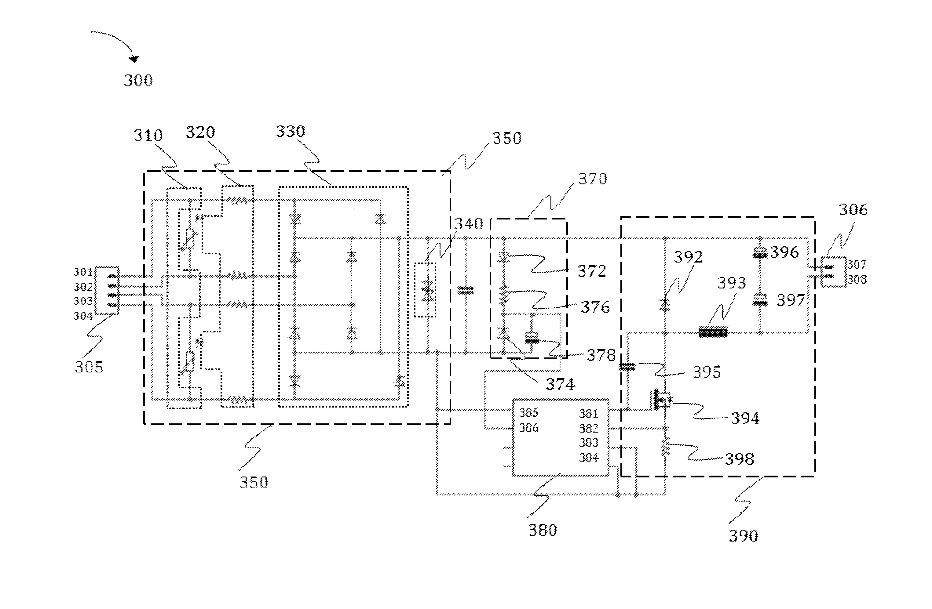
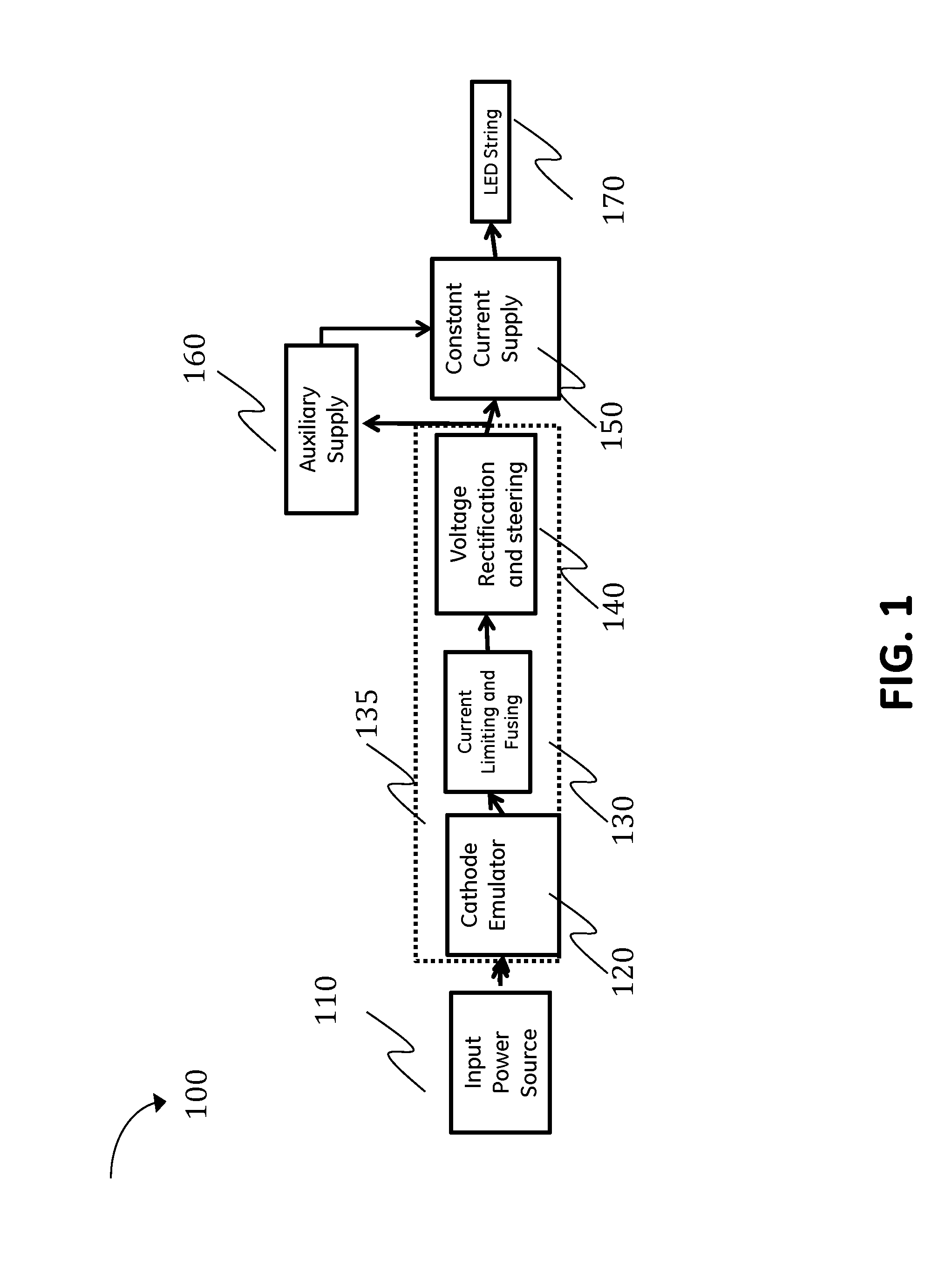
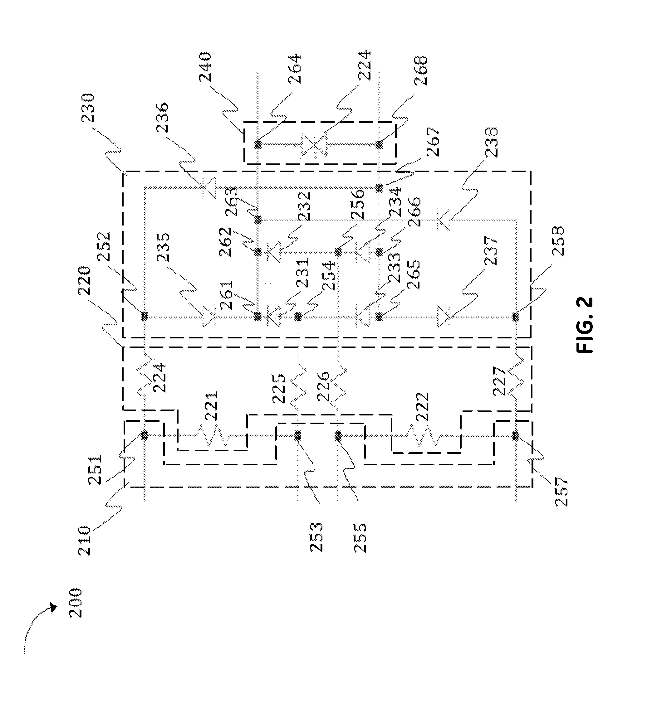
[0009]Based on the aforementioned failures associated with driver replacement, there exists a need for an LED driver circuit that does not require the rewiring of a fixture when connected to a fluorescent tube lamp ballast. That is, a need exists for an LED driver circuit that can work with all ballast types, including instant start, rapid start and program stat fluorescent ballasts. Additionally, the LED replacement driver circuit will limit the possible high voltage normally provided by the LFL ballast. Embodiments of the present invention provide an LED replacement driver circuit comprising a cathode emulator, a voltage steering and rectifier, which allows the driver circuit to serve as a universal replacement driver circuit that is agnostic to the ballast structure.

[0010]One benefit of a universal replacement driver is it allows an LED driver to be installed in a fluorescent tube lamp ballast. The lighting industry has explored ways to replace the standard fluorescent light bulb...


PUM


Abstract

Provided is a circuit replacement device for a light emitting diode (LED) tube lamp. The circuit includes a cathode emulator configured for (i) coupling to an input power source and (ii) emulating operation of a fluorescent lamp cathode. Also included is a rectification mechanism having an input port coupled to an output of the cathode emulator and an output port configured for coupling to at least one from the group including a current supply and an output load.

Description

I. FIELD OF THE INVENTION[0001]The present invention relates generally to replacement linear fluorescent tube lamps with light emitting diode (LED) drivers.II. BACKGROUND OF THE INVENTION[0002]LEDs have rapidly increased in lighting applications due to their efficiency and lifetime sustainability over fluorescent lamps. LEDs are mercury free light sources, requiring a direct current (DC) voltage or current to operate optimally. Operating on a current controlled power supply enables LEDs to achieve high lumens per watt efficiency, constant color temperature, and high color rendering. Additionally, with a potential lifetime of 100,000 hours, LEDs virtually eliminate maintenance and replacement costs associated with linear fluorescent lights.[0003]In a typical fluorescent tube lamp, a ballast is used to regulate the current flow through the tube lamp so that the current does not rise to a level that would destroy the lamp. As such, the type of ballast selected for a lighting applicatio...

Claims


Application Information

Patent Timeline
IPC IPC(8): H05B33/08H05B44/00
CPCH05B33/0812Y02B20/30H05B45/375H05B45/3725H05B45/38H05B45/395H05B45/385
Inventor ROBERTS, BRUCE RICHARD
Owner GE LIGHTING SOLUTIONS LLC
Learn More