
Monitoring systems and methods

Inactive Publication Date: 2015-06-18
TDG AEROSPACE
View PDF7 Cites 44 Cited by
  • Summary
  • Abstract
  • Description
  • Claims
  • Application Information

AI Technical Summary

Benefits of technology

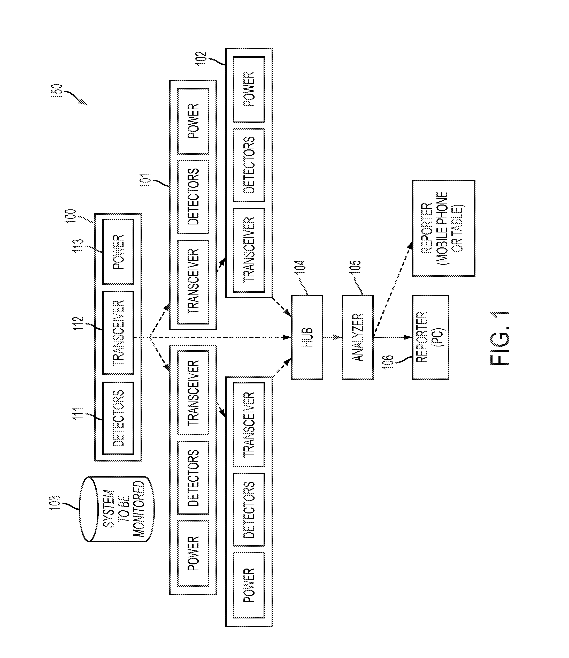
The present invention provides a monitoring system for monitoring a group of motors in a closed geographic area to determine their operating condition. The monitoring system comprises a plurality of modules, a hub computer, and an analyzer computer. The modules are adapted to sense vibrations and temperature in close proximity to the motor assembly and transmit the data to the hub computer. The hub computer collects the data and sends it to the analyzer computer. The analyzer computer analyzes the data and alerts when a threshold is reached. The system can also include a memory that stores parameters for the operation of the modules and a battery holder for each module. The system can also include a remote module that senses and reports the frequency of a variable frequency drive signal that is applied to a motor assembly. The system can be used with other devices such as a diagnostic forecasting system that predicts the expected life of the motor assembly.

Problems solved by technology

Known prior art systems have been deficient in meeting the combination of performance, cost, and durability in the field monitoring systems for mechanical motor operation in industrial applications having critical fire or operational demands.
Known systems have deficiencies such as they often times implement complex processing at a sensor assembly which can drain battery power and may delay the rate of reporting of conditions to a central device.
Such systems are also often times bulky or have a significant profile for the purpose of ease of manufacture or ease of maintenance (e.g., so that a technician can easily access all components by opening the sensor assembly).
Known systems are also often times deficient because they lack the necessary robust wireless capability and power requirements to be able to carry out higher level protocol functionality and to cover contiguous physical areas with potentially lower power transceivers.
These and other deficiencies are evident in the prior art.

Method used


Image

  • Monitoring systems and methods
  • Monitoring systems and methods
  • Monitoring systems and methods

Examples


Embodiment Construction

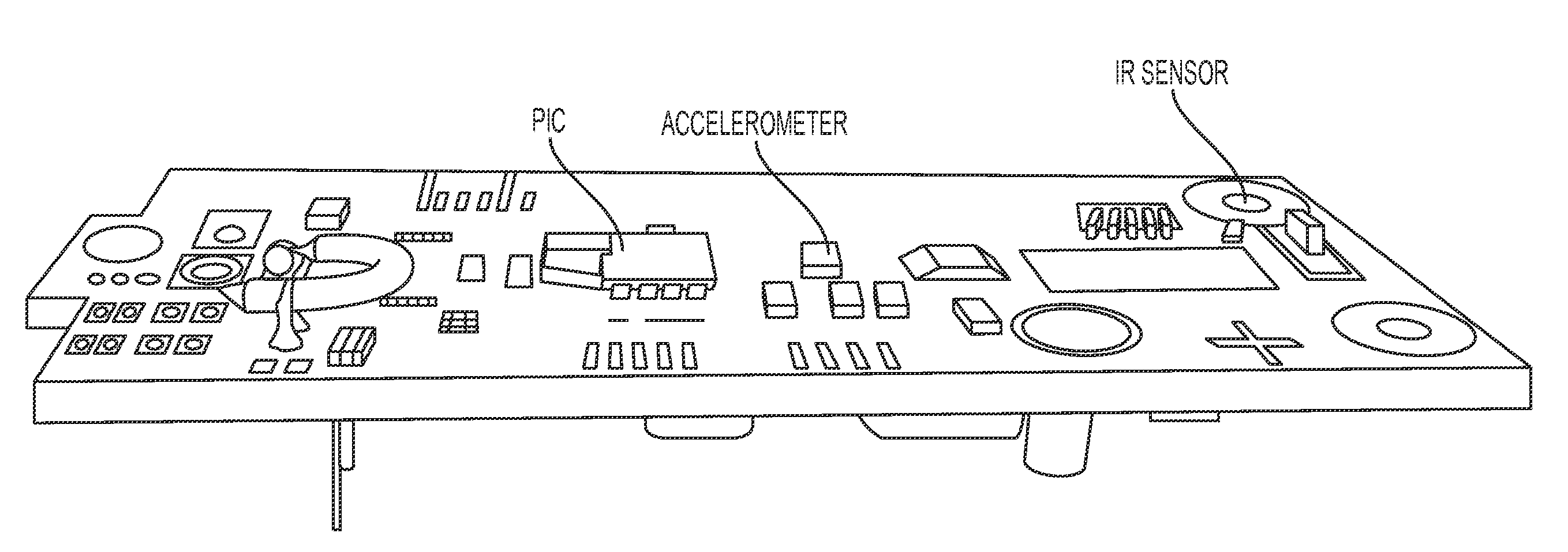
[0026]Systems and methods according to one or more embodiments of the invention provide elegant, efficient, and cost effective options for monitoring the operating condition of mechanical components of fuel farms or if desired other electromechanical systems having motors or rotating components. By monitoring mechanical operation of components such as motors and their environment, systems and methods can allow a human operator to make early decisions to determine whether to perform diagnostics or conduct physical inspection of components. The systems and methods combine different features to provide modules and monitoring systems that outperform prior art systems such as by being power efficient, being cost effective, having a low profile, and having other performance characteristics. Existing known systems do not provide combinations of benefits and performance illustratively described herein.

[0027]Referring to FIG. 1, one embodiment of the monitoring system for monitoring a motor ...


PUM


Abstract

A monitoring system includes a plurality of modules to sense temperature and vibrations of a motor assembly, a hub computer to collect the sensed temperature and vibrations, and an analyzer computer to analyze the collected temperature and vibrations. The modules contain detectors that measure a temperature and vibrations in three axes of the motor assembly, a transceiver integrated circuit that measures a die temperature of the transceiver integrated circuit, a microcontroller integrated circuit that self-adjusts its clock pulses, and a memory that stores parameters set for the operation of the modules. The microcontroller integrated circuit and the memory are configured to check parameters corruption upon transferring the parameters from the memory to the microcontroller integrated circuit and prior to utilizing by the microcontroller integrated circuit. The modules further have an enclosure that is compact in size and that can withstand severe industrial environment.

Description

CROSS REFERENCE TO RELATED APPLICATIONS[0001]This application claims the benefit of U.S. Provisional Application No. 61 / 916,592, filed on Dec. 16, 2013 and U.S. Provisional Application No. 62 / 059,781, filed Oct. 3, 2014. The disclosure of U.S. Provisional Application No. 61 / 916,592 and U.S. Provisional Application No. 62 / 059,781, filed Oct. 3, 2014 are hereby incorporated into by reference.FIELD OF INVENTION[0002]The present application relates to the field of monitoring mechanical systems having multiple motor assemblies in a closed geographic area, in particular with innovative techniques for monitoring the current operating status of the motor assemblies.BACKGROUND OF THE INVENTION[0003]Known prior art systems have been deficient in meeting the combination of performance, cost, and durability in the field monitoring systems for mechanical motor operation in industrial applications having critical fire or operational demands. Known systems have deficiencies such as they often time...

Claims


Application Information

Patent Timeline
IPC IPC(8): G01M99/00G01K13/00G01H1/00
CPCG01M99/00G01K13/00G01H1/003G01K2205/00G01R31/343G01M7/00G05B23/0235
Inventor FISH, DANIEL E.EVANS, DAVID L.SKINNER, TODD B.WAGNER, ANDREWALTING-MEES, ADRIAN
Owner TDG AEROSPACE
Learn More