
Gesture Recognition

a technology of finger and finger, applied in the field of finger recognition, can solve the problems of reducing transparency, increasing construction costs, and difficulty in scaling up the screen siz

Active Publication Date: 2009-11-05
SOLAS OLED LTD
View PDF55 Cites 283 Cited by
  • Summary
  • Abstract
  • Description
  • Claims
  • Application Information

AI Technical Summary

Benefits of technology

[0018]The gesture recognition code can be written in a high level language such as C and then compiled and embedded in a microcontroller chip, or CPU chip as desired. Preferably, the gesture recognition code is loaded into the same chip that interprets the touch signals from the screen and generates the time series data, e.g. a microcontroller, or other programmable logic device such as a field programmable gate array (FPGA). This approach has been used to create reliable testable code both for single-touch data input screens and also multi-touch data input screens. A single-touch screen is one which assumes only one simultaneous touch of the screen, and is designed to output only one x,y coordinate at any one time. A multi-touch screen is one that can sense multiple simultaneous touches, for example up to 2 or 3 simultaneous touches.

Problems solved by technology

However this scheme requires numerous secondary electrode connections as well as two or more layers of construction, increasing construction costs and reducing transparency.
However this patent suffers from the problem that it is difficult to scale up the screen size, as the number of electrode connections to a sensing circuit is one per triangle.
Most of the patent literature is unspecific about how the raw time series data are converted into gestures.
However, it is difficult to reliably and efficiently add code to identify a new gesture into an existing block of code for distinguishing between a significant number of gestures, for example at least 3 or 4, perhaps 10 to 20.
Testing of the code is a particular difficulty.

Method used


Image

  • Gesture Recognition
  • Gesture Recognition
  • Gesture Recognition

Examples


first embodiment

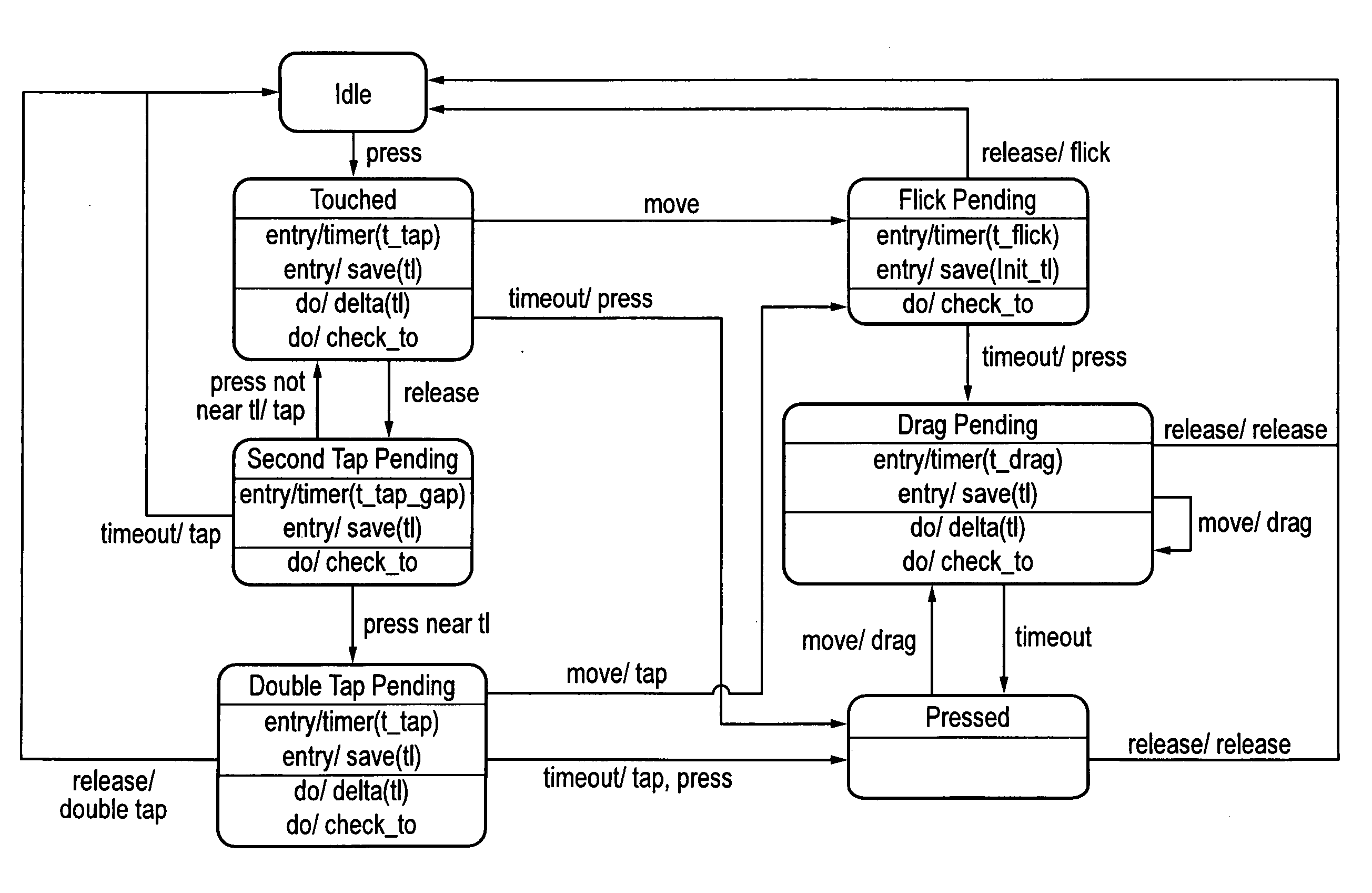
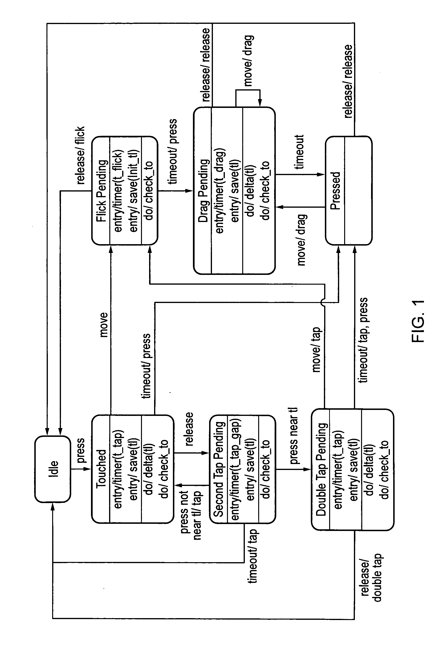
[0078]FIG. 1 shows a state machine for gesture recognition which is limited to processing gestures made up of single touches. In other words, multitouch gestures are not catered for in this embodiment. The supported gestures are: tap; press; double tap; flick; and drag. These 5 gestures are recognized in the state machine by traversing 7 states interconnected by approximately 17 transitions, as illustrated in the figure. The states can be further subdivided into those relating to static touches, namely press, tap and double tap in this example, and those related to moving touches, namely flick and drag in this example.

[0079]The Idle state is now described. The Idle state occurs whenever a user is not touching the touch surface. There are no actions triggered by entering this state, and no actions performed while in this state. The Idle state will undergo a transition into a Touched state if the user presses the touch surface with one finger. The Idle state has no parameters, and th...

second embodiment

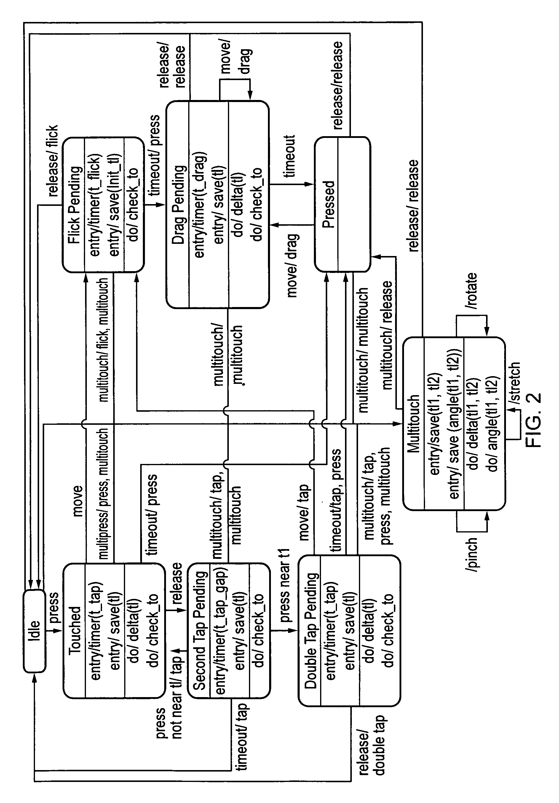
[0105]It would also be difficult to extend the state machine of the second embodiment to handle gestures involving more than two touches. The state machine complexity would grow rapidly with each additional touch.

[0106]These limitations are overcome by a fourth embodiment of the invention according to which the multitouch state is removed from the state machine of the second embodiment to return to a simple single-touch state machine according to the first embodiment as shown in FIG. 1. A single-touch state machine of this kind can track all of the required information from a single touch. Multiple single-touch state machines are then combined to handle multiple touch gestures instead of creating a more complex multi-touch state machine following the approach of the second embodiment.

fourth embodiment

[0107]FIG. 4 shows at its highest conceptual level a state machine according to the In this diagram, the ‘Touch x’ blocks each represent the single-touch state machine in FIG. 3. ‘N’ such state machines are processed by an N-touch state machine to generate N-touch gestures.

[0108]FIG. 5 shows internal structure of the N-touch state machine of the second embodiment, which comprises idle and touched states. If all touches are pressed, the state machine is in the N-Touch Touched state, otherwise it is in the N-Touch Idle state. The state machine can generate events in either state. For instance, when in the N-Touch Touched state, if all of the 1-touch state machines are in the drag pending state, an N-Touch Drag event could be generated when any of them generate a Drag event.

[0109]FIG. 6 shows how this approach can be used to give equivalent functionality to the state machine of the second embodiment shown in FIG. 2, but with a simpler scalable architecture.

[0110]In this example, Touch...


PUM


Abstract

A state machine gesture recognition algorithm for interpreting streams of coordinates received from a touch sensor. The gesture recognition code can be written in a high level language such as C and then compiled and embedded in a microcontroller chip, or CPU chip as desired. The gesture recognition code can be loaded into the same chip that interprets the touch signals from the touch sensor and generates the time series data, e.g. a microcontroller, or other programmable logic device such as a field programmable gate array.

Description

BACKGROUND OF THE INVENTION[0001]The invention relates to gesture recognition in particular gesture recognition by processing of time series of positional inputs received by a two-dimensional (2D) touch sensor, such as a capacitive or resistive touch sensor. The invention may also be applied to one-dimensional (1D) touch sensors, and the principles could also be applied to three-dimensional sensors. It may also be applied to proximity sensors, where no physical contact, i.e. touch, with a sensing surface is involved. The invention can be applied to sensing surfaces operable by a human finger, or a stylus.[0002]1D and 2D capacitive and resistive touch sensors have been in widespread use for many years. Examples include the screens of personal digital assistants (PDAs), MP3 audio player controls, mobile phone keypads and / or displays, and multimedia devices. The touchpad in notebook computers provided in place of a mouse is another form of 2D capacitive touch sensor. 2D sensors are als...

Claims


Application Information

Patent Timeline
IPC IPC(8): G06F3/041
CPCG06F3/03547G06F3/044G06F3/041G06F3/04883G06F2203/04808G06F3/045G06F3/0446G06F3/0445
Inventor BOWENS, ALAN
Owner SOLAS OLED LTD
Learn More