
Purification System Comprising Continuous Reactor and Purification Method Using Continuous Reactor

a technology of purification system and continuous reactor, which is applied in the direction of vibration crystallization, separation process, filtration separation, etc., can solve the problems of difficult to obtain crystals having a transmission of 95% or higher, shorten the regenerative cycle of resin, and difficult to achieve dark spots in the device. , the effect of prolonging the life of the devi

Inactive Publication Date: 2015-06-18
LAMINAR
View PDF0 Cites 5 Cited by
  • Summary
  • Abstract
  • Description
  • Claims
  • Application Information

AI Technical Summary

Benefits of technology

The present invention provides a method for producing high-purity organic materials in large amounts using a crystallization method. By using a continuous reactor and adding a polymer material, the recovery rate of tryptophan is increased and the purity of the material is improved to 99.9% or higher. This method also reduces dark spots in devices made from the organic material, improves electrical and optical properties, and extends the lifespan of the device. The resulting high-purity organic material can be used to fabricate organic electroluminescent devices with improved performance and longevity.

Problems solved by technology

However, it was found that the method employing an ultrafiltration membrane as disclosed in Japanese Patent Laid-Open Publication No. 1983-895 could not remove impurities at a fixed removal rate, and thus excessive load was applied to a non-polar highly porous resin to shorten the regenerative cycle of the resin.
In addition, in the case of the method disclosed in Japanese Patent Laid-Open Publication No. 1984-39857, the degree of removal of impurity is low and it is difficult to obtain a crystal having a transmission of 95% or higher.
Moreover, the method disclosed in Japanese Patent Laid-Open Publication No. 1986-126070 has a problem in that, particularly when a reaction solution, prepared by a fermentation process and containing large amounts of impurities, is heated at a temperature of 95˜100° C. in the presence of activated carbon, the amount of a degraded and colored substance increases because tryptophan contains an unstable indole ring in its structure.

Method used


Image

  • Purification System Comprising Continuous Reactor and Purification Method Using Continuous Reactor
  • Purification System Comprising Continuous Reactor and Purification Method Using Continuous Reactor
  • Purification System Comprising Continuous Reactor and Purification Method Using Continuous Reactor

Examples


embodiment 1

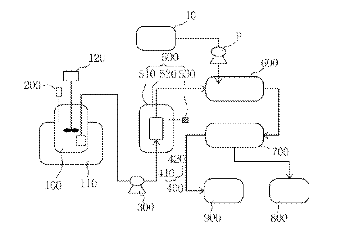
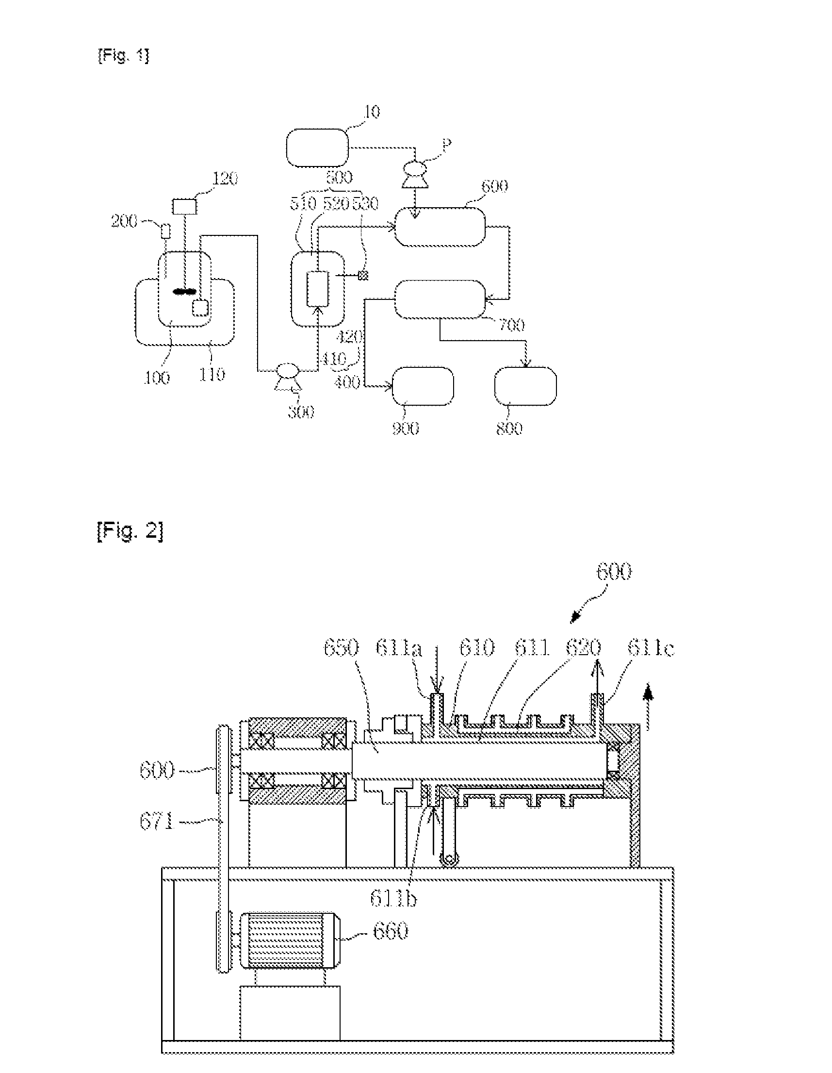
[0029]The purification system shown in FIGS. 1 to 3 comprises a reactor. This purification system comprises a solution storage tank 100, an ultrasonic disperser 200, an air compressor 300, a filter cartridge 400, a temperature controlling unit 500, a continuous reactor 600, an organic material separator 700, an organic material storage chamber 800 and a correction module 900.

[0030]The solution storage tank 100 serves to store a solution of an organic material (OLED) in an organic solvent. The concentration of the organic material in the organic solvent is preferably 100 g / L or lower, and if the concentration of the organic material is higher than the upper limit of the above concentration range, a crystallization reaction will be delayed or it will be difficult to obtain the desired purity. As used herein, the term “organic material” refers to any material that is provided between the anode and cathode of an organic electroluminescent device. Examples of an organic material or organ...

embodiment 2

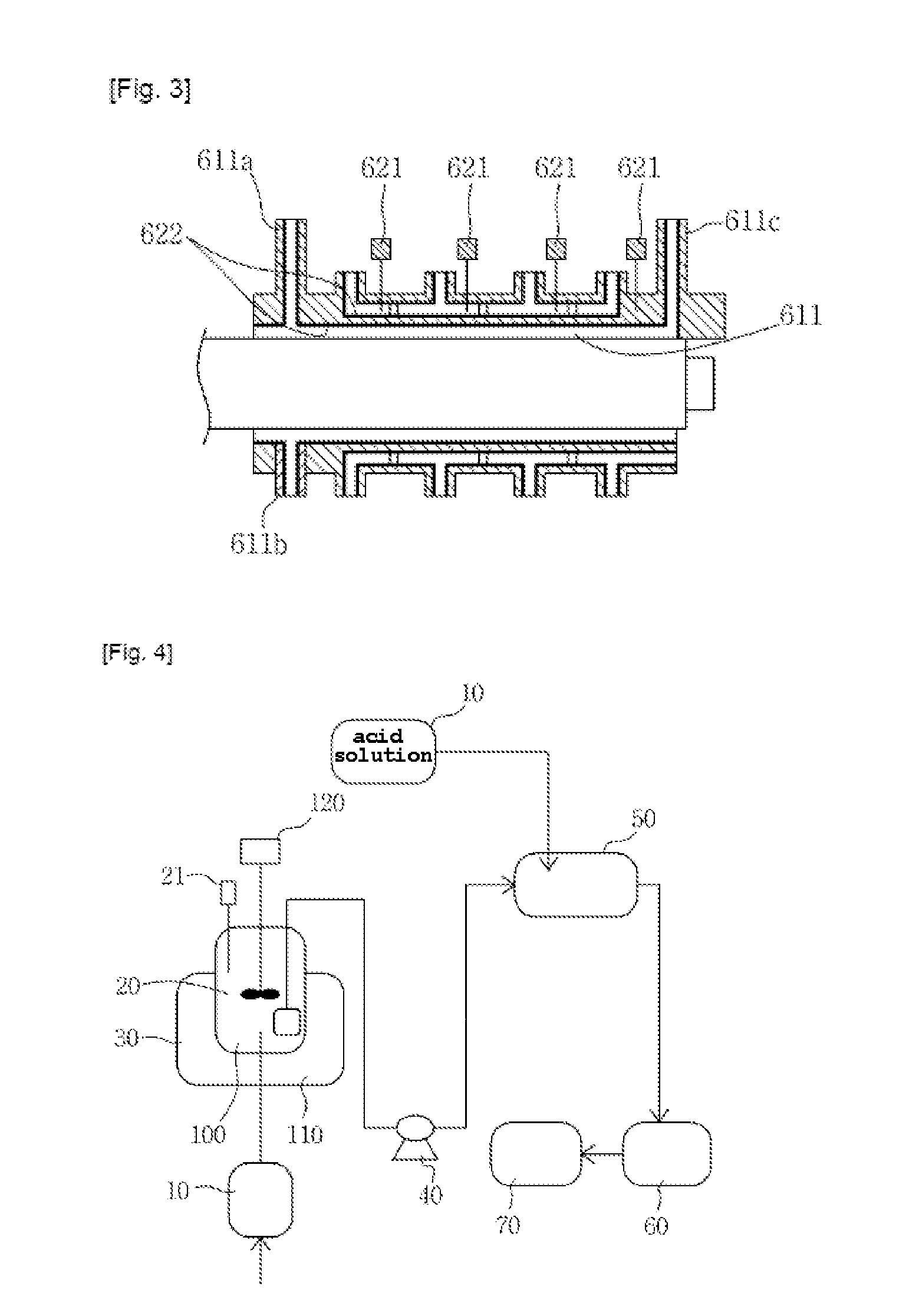
[0054]Hereinafter, a system for purifying tryptophan will be described which comprises, in addition to the above-described continuous reactor, storage tank, stirrer, disperser and heating jacket, a dewaterer and a dryer.

[0055]As shown in FIG. 4, the system for purifying tryptophan comprises a filter 10 for filtering solids, a storage tank 20, a heating tank 30, an air compressor 40, a continuous reactor 50, a dewaterer 60 and a dryer 70.

[0056]The filter 10 for filtering solids is configured to filter out solids from a tryptophan solution while allowing the solution to pass through the filter. Herein, the filter 10 has a mesh size (or pore size) of 0.1 μm or larger, and preferably 0.1-0.5 μm, so that it filters out solids having a size of 0.5 μm or larger from the tryptophan solution and allows only fine solids having a size of less than 0.5 μm to pass therethrough. As a result, the filter 10 performs a first purification step. The storage tank 20 serves to store the tryptophan solut...

embodiment 3

[0062]A method for purifying tryptophan according to the present invention is performed in the following order (see FIG. 5).

[0063]Step 1 is a solid removal step (S10).

[0064]In the solid removal step, the tryptophan solution is passed through a filter to remove solids having a size larger than a predetermined size, before it is stored in the storage tank.

[0065]The filter that is used in the solid removal step preferably has a mesh size (or pore size) of 0.1-0.5 μm. Thus, dissolved solids having a size of 0.5 μm or larger, contained in the tryptophan solution, are filtered out, and thus the tryptophan solution contains only fine solids having a size smaller than 0.5 μm.

[0066]Step 2 is a pH adjusting step (S20).

[0067]In the pH adjusting step, caustic soda (NaOH) is introduced into the storage tank to adjust the pH of the tryptophan solution. Herein, the pH is preferably adjusted to 3-11.

[0068]Step 3 is a temperature controlling step (S30).

[0069]In the temperature controlling step, the ...


PUM

PropertyMeasurementUnit
Temperatureaaaaaaaaaa
Poweraaaaaaaaaa
Electrical resistanceaaaaaaaaaa

Abstract

The present invention relates to a purification system configured such that a solution stored in a solution storage tank is dispersed / stirred ultrasonically and sent by an air compressor to a reactor in which the sent solution and a solvent introduced through another pathway are stirred to produce a reaction product, and a purification method using the purification system.

Description

TECHNICAL FIELD[0001]The present invention relates to a purification system comprising a continuous reactor. More particularly, the present invention relates to a purification system configured such that a solution stored in a solution storage tank is dispersed / stirred ultrasonically and sent by an air compressor to a reactor in which the sent solution and a solvent introduced through another pathway are stirred to produce a reaction product, and a purification method using the purification system.BACKGROUND ART[0002]Generally, many materials need to be purified. Similarly, organic materials, as well as essential amino acids that are used in feed additives, medical drugs, health foods and the like, need to be purified. For example, organic materials that are used for organic light-emitting devices are pure target components separated from synthesized materials and are used for thin film deposition. With improvement in technology for purifying organic materials, the luminous efficien...

Claims


Application Information

Patent Timeline
IPC IPC(8): B01D9/00C07D209/20
CPCB01D9/0081B01D2009/0095C07D209/20B01D9/0063B01D9/00B01D9/0054C07D209/16B01D36/00B01J19/0013B01J19/10B01J19/18B01J2219/00033B01J2219/00094B01J2219/00103
Inventor HONG, JONG PALLEE, CHIL WONLEE, HEE WANCHOI, GYEONG RYE
Owner LAMINAR
Learn More