
Time/wavelength-division multiplexed passive optical network (TWPON)

a passive optical network and time/wavelength division technology, applied in the field of passive optical networks, can solve the problems of increasing the cost of using higher speed transceivers, the structure of tdm-pons may not meet the needs, and the power budget might be a problem, so as to increase the transmission capacity, and reduce the number of wavelengths

Active Publication Date: 2015-06-11
NAT TAIWAN UNIV OF SCI & TECH
View PDF40 Cites 3 Cited by
  • Summary
  • Abstract
  • Description
  • Claims
  • Application Information

AI Technical Summary

Benefits of technology

[0011]An objective of the present invention is to provide a time / wavelength-division multiplexed passive optical network (TWPON) for giving much flexibility to increase transmission capacity and the number of users.
[0016]Compared to a traditional time-division multiplexed passive optical network (TDM-PON), the TWPON implemented according to the present invention can carry out high-capacity transmission at relatively low cost, and does not have a problem of unable to increase transmission capacity in the traditional TDM-PON, caused by the limitation of high-speed transceivers themselves. Compared to a traditional WDM-PON, the TWPON implemented according to the present invention can use less numbers of wavelengths to carry out the same transmission capacity, and meanwhile occupied optical wavelength bands are relatively small and the cost of used light sources is relatively low as well. The TWPON of the present invention can efficiently integrate and access to the network as desired, is able to provide different services in response to different demands for transmission bandwidth, and also can increase transmission capacity at relatively low cost in response to the increasing of users.

Problems solved by technology

The TDM-PON structure may not serve the needs when the demand for larger bandwidth is increased.
This is because it might be more difficult in system design and costly to use higher speed transceivers that are required in 40G-PON or 100G-PON.
Also, power budget might be a problem.
However, the WDM-PON structure is costly.
However, the DWDM transceivers and colorless light sources are still quite expensive.
The tunable OTDR is relatively high in cost and the use of the tunable OTDR requires a larger optical bandwidth for the channel monitoring.

Method used


Image

  • Time/wavelength-division multiplexed passive optical network (TWPON)
  • Time/wavelength-division multiplexed passive optical network (TWPON)
  • Time/wavelength-division multiplexed passive optical network (TWPON)

Examples


first embodiment

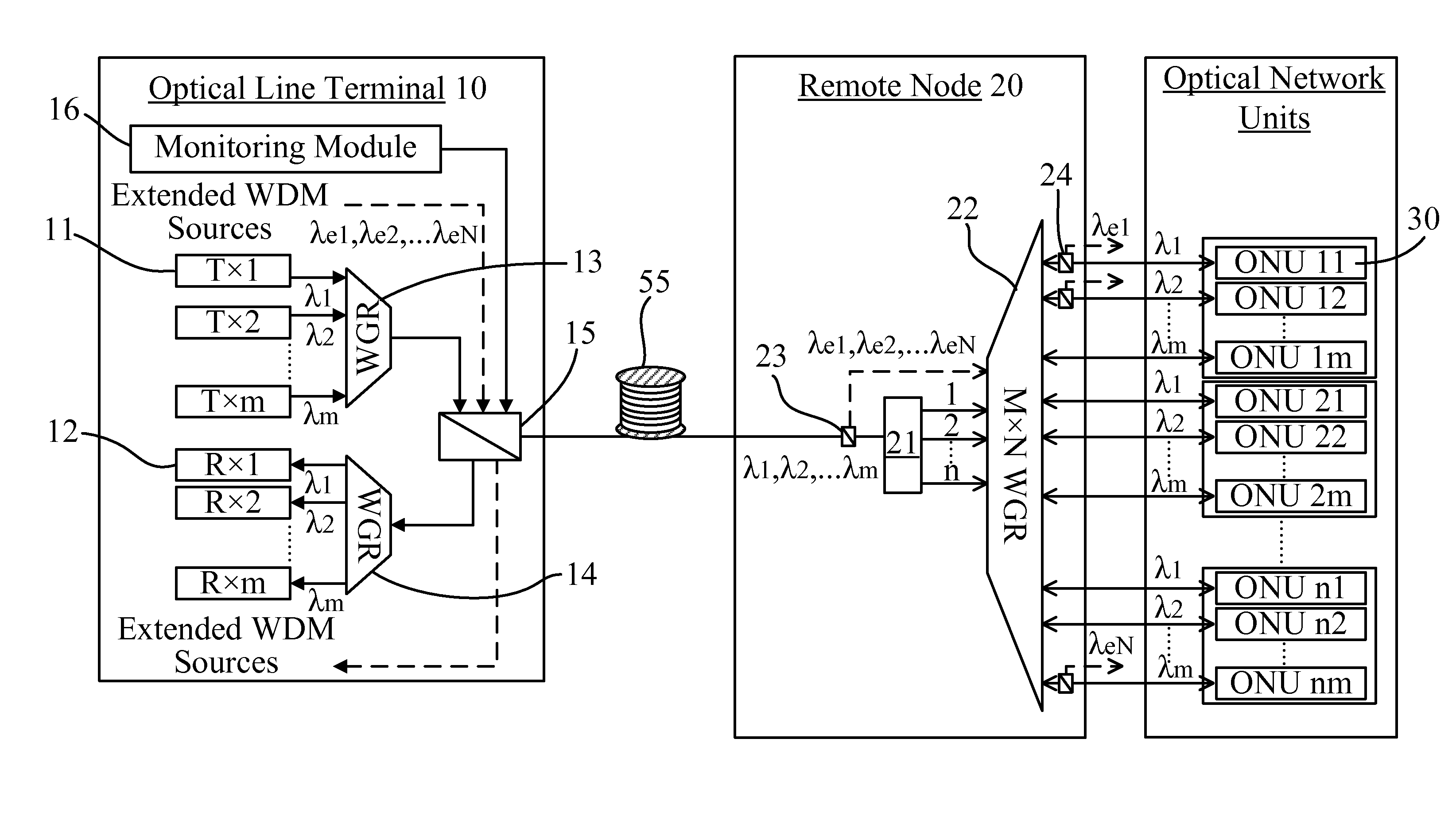
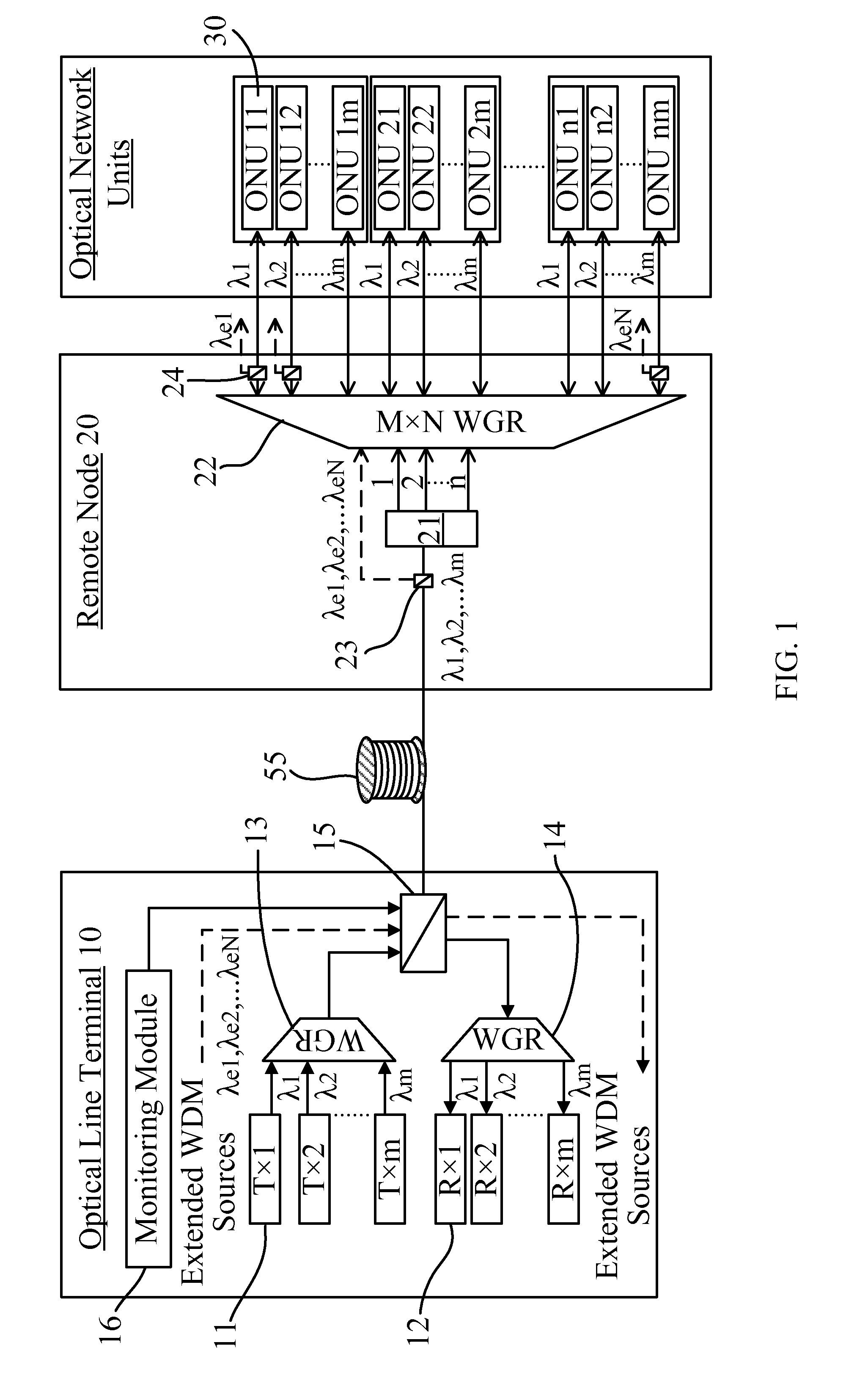
[0029]Referring to FIG. 1, the TWPON of the present invention further comprises a wavelength band filter 23 disposed at the RN 20. The wavelength band filter 23 is coupled to the optical splitter 21 and the WGR 22. The wavelength band filter 23 can make the mixed optical signal {λ1, λ2, . . . λm} from the OLT 10 to pass the optical splitter 21 and make another mixed optical signal {λe1, λe2, . . . λeN} from the OLT 10 to pass one of the input ports of the WGR 22 such that the mixed optical signal {λ1, λ2, . . . λm } is merely allowed to enter the optical splitter 21 and said another mixed optical signal {λe 1, λe2, . . . λeN} is merely allowed to enter one of the input ports of the WGR 22. Moreover, the WGR 22 will respectively output component signals of said another mixed optical signal {λe1, λe2, . . . λeN} to predetermined ONUs 30. As shown in FIG. 1, a WDM band filter 24 may be arranged between each output port of the WGR 22 and corresponding ONU 30. The WDM band filter 24 is u...

second embodiment

[0039]A channel fault monitoring (CFM) module 16 located at the OLT 10 can be utilized to locate fiber breaks among distribution fibers. In the present invention, the channel fault monitoring can follow any of the signal paths of the three classes of services by using a wavelength band that is an integer multiplicity of λFSR away from the signal band and a suitable band filter. However, it also can merely use the Hybrid PON path because of its compromised optical bandwidth and splitting loss for the monitoring signal. This can be implemented by using a tunable laser or a broadband light source that covers an optical bandwidth of n wavelengths rather than N wavelengths. In such a manner, the number of used wavelengths for the channel fault monitoring is reduced efficiently. If the number of the shared ONUs 30 is relatively small (e.g, m=4), the OTDR should be able to resolve the reflected signals or the distribution fibers can easily arranged to have different lengths among the share...

fourth embodiment

The advantage of the present invention is that the TDM-PON transmission does not have extra insertion loss from the WGR 28.


PUM


Abstract

The present invention discloses a time / wavelength-division multiplexed passive optical network (TWPON), which has an optical splitter (21) and a waveguide grating router (WGR) (22) disposed at a remote node (RN) (20). The optical splitter (21) and the WGR (22) can be connected in a cascade or in a parallel such that the present invention can use less number of wavelengths to increase transmission capacity or increase the number of users. A channel fault monitoring (CFM) module provided at an optical line terminal (OLT) is utilized to locate fiber breaks among distribution fibers. The TWPON of the present invention can provide TDM-PON, WDM-PON, and Hybrid PON co-existing platform with less wavelengths channel fault monitoring mechanism.

Description

CROSS REFERENCE TO RELATED APPLICATION[0001]This is a division of a U.S. patent application Ser. No. 13 / 527,573, filed on Jun. 19, 2012.TECHNICAL FIELD OF THE INVENTION[0002]The present invention relates to a passive optical network (PON), and more particularly, to a passive optical network capable of giving much flexibility to increase transmission capacity and the number of users.BACKGROUND OF THE INVENTION[0003]Generally, a passive optical network comprises an optical line terminal (OLT), a remote node (RN), and a plurality of optical network units (ONUs). A terminal such as a personal computer (PC) is connected to the ONU and the ONU will transform a signal transmitted from the terminal into an optical signal. The optical signal is split by an optical splitter at the RN and then transmitted to a central office (CO) of a service provider, i.e., the aforesaid OLT, through an optical fiber. After the OLT performs various types of signal processing, communication between one ONU and...

Claims


Application Information

Patent Timeline
Patent Type & Authority Applications(United States)
IPC IPC(8): H04J14/08H04J14/02
CPCH04J14/02H04J14/08H04J14/0232H04J14/0246H04J14/0282H04J14/0235H04J14/0227H04J14/0247H04J14/025H04J14/0252H04J14/0265
Inventor LEE, SAN-LIANG
Owner NAT TAIWAN UNIV OF SCI & TECH
Learn More