
System And Method For Generating A Dynamic Three-Dimensional Model

a three-dimensional model and dynamic technology, applied in the field of system and method for generating a dynamic three-dimensional model, can solve the problems of limited use and/or high cost, inability to use for professional purposes, and high cost of the apparatus developed for this purpose available on the mark

Inactive Publication Date: 2015-06-11
ZINEMATH ZRT
View PDF6 Cites 79 Cited by
  • Summary
  • Abstract
  • Description
  • Claims
  • Application Information

AI Technical Summary

Benefits of technology

The invention provides a system and method for creating a realistic and dynamic three-dimensional model of a space. It records depth information in real-time, in addition to image information, and can be used in various fields like film, safety engineering, military technology, and industrial automation. The system is easy to install, provides real-time feedback, and is accurate even in offline or online processing. Additionally, it can be used both indoors and outdoors under complicated environmental conditions.

Problems solved by technology

These procedures are supported by several products on the market, but they have a limited use and / or are very expensive.
Of course, the manufacturers are making efforts to meet these requirements, but known solutions are burdened with a number of problems for which no complex solution has been found so far.
The apparatuses developed for this purpose available on the market are very expensive, and therefore only used for high budget films, or they are inaccurate and therefore cannot be used for professional purposes.
Furthermore, they generally require considerable post-production (which represents a high cost by way of example in the case of a film, because of the high number of post-production hours), and therefore they are not adapted for real-time processing (like, for example, a live TV report) either.
In addition, the currently available apparatuses generally have a large (extensive) size.
The resolution of laser ranging sensors is heavily limited, and most LIDARs only measure in one plane.
Even the more developed and more expensive units (like for example laser ranging sensors with a rotating head) provide data about the environment with a resolution of max.
Laser ranging does not provide data about the trajectory of the recording apparatus.
559-568, 2011); the film industry has also discovered for itself the so-called Kinect sensor adapted also for identifying the space, but the film-related application of the apparatus according to the document and the solutions based on the apparatus are very much limited.
The Kinect sensor does not provide information about its own movement, and such systems available on the market only operate with a standing, fixed camera.
This method does not require a lot of facilities, and therefore it is low priced, but it is very much labour intensive, and in many cases not sufficiently accurate.
This position identification method requires the preliminary installation and calibration of the sensors and the co-ordinated work of several people, and therefore the related cost is high.
However, a serious disadvantage is its slowness.
A further disadvantage of the method is that only the picture of a camera moving in space can be used for it.
In a so-called ‘green screen’ studio environment, only limited use is possible, because there are no trackable and well-identified points in the homogeneous background.
A further problem of the method is that it is necessary to remove from the image somehow, characteristically by a hand-drawn and animated mask, the elements (for example vehicles, people) which are in motion compared to the reference points, because if the points thereon are also tracked by the software, this will result in an erroneous trajectory of the camera.
In addition, the so-called pseudo-feature points, i.e. the not well usable identified points like reflections, rounded edges or the so-called T-nodes can be a serious problem, and generally demand manual correction.
The applied identified and tracked points only provide low resolution, ad hoc information about the space, and on this basis the model of the space may only be generated by considerable human intervention.
The use of these mechanical means is difficult, and they have a relatively low accuracy.
Their use may not be matched to the application of hand-held cameras or cameras moved without special camera manipulators, and therefore the utilisation of a mechanical sensor environment is very expensive.
The sensor environment does not provide information on the structure of the space.
It is a disadvantage that implementation is very costly.
Not only the hardware environment applied in the method is expensive, but the installation and calibration of the system also demand the work of several people, and therefore this solution is characteristically used in a studio environment, with fixed installation.
A further disadvantage of this solution is that it only monitors and specifies the camera position, and does not register any data about the structure of the space, and demands that a specified part of the sensors see the tracked camera continuously.

Method used


Image

  • System And Method For Generating A Dynamic Three-Dimensional Model
  • System And Method For Generating A Dynamic Three-Dimensional Model
  • System And Method For Generating A Dynamic Three-Dimensional Model

Examples


Embodiment Construction

[0021]The primary object of the invention is to provide a system and method for generating a dynamic three-dimensional model of a space (a part of the space or a space part), which are free of the disadvantages of prior art solutions to the greatest possible extent.

[0022]A further object of the system and method according to the invention is to apply more efficient processing than the known solutions, preferably filtering and probability estimation, to provide more accurate data about the structure of the space than the known solutions.

[0023]The system according to the invention also records depth information in real-time, in addition to the image (optical) information. In addition to the application in the film industry, the system according to the invention may be useful in many other areas as well (safety engineering, military technology, industrial automation, etc.), but the solution basically focuses on meeting the requirements of the film industry and eliminating the problems ...


PUM


Abstract

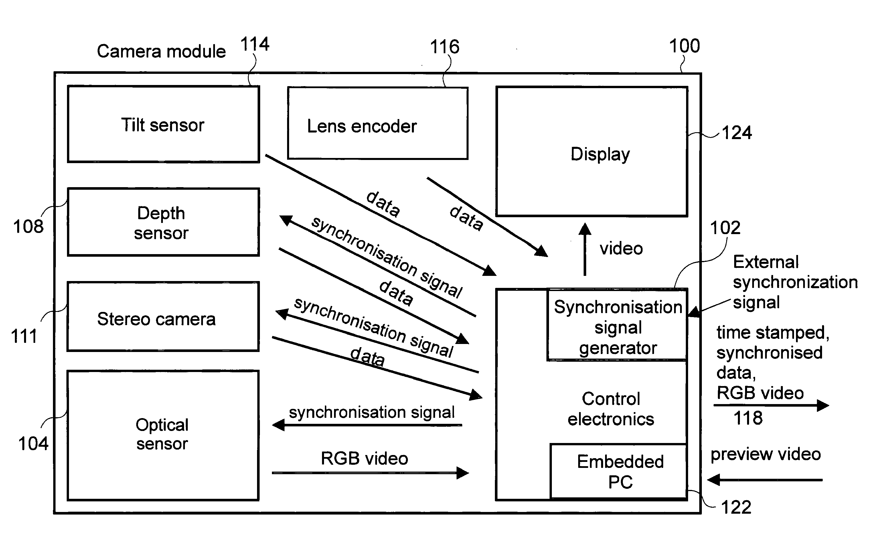
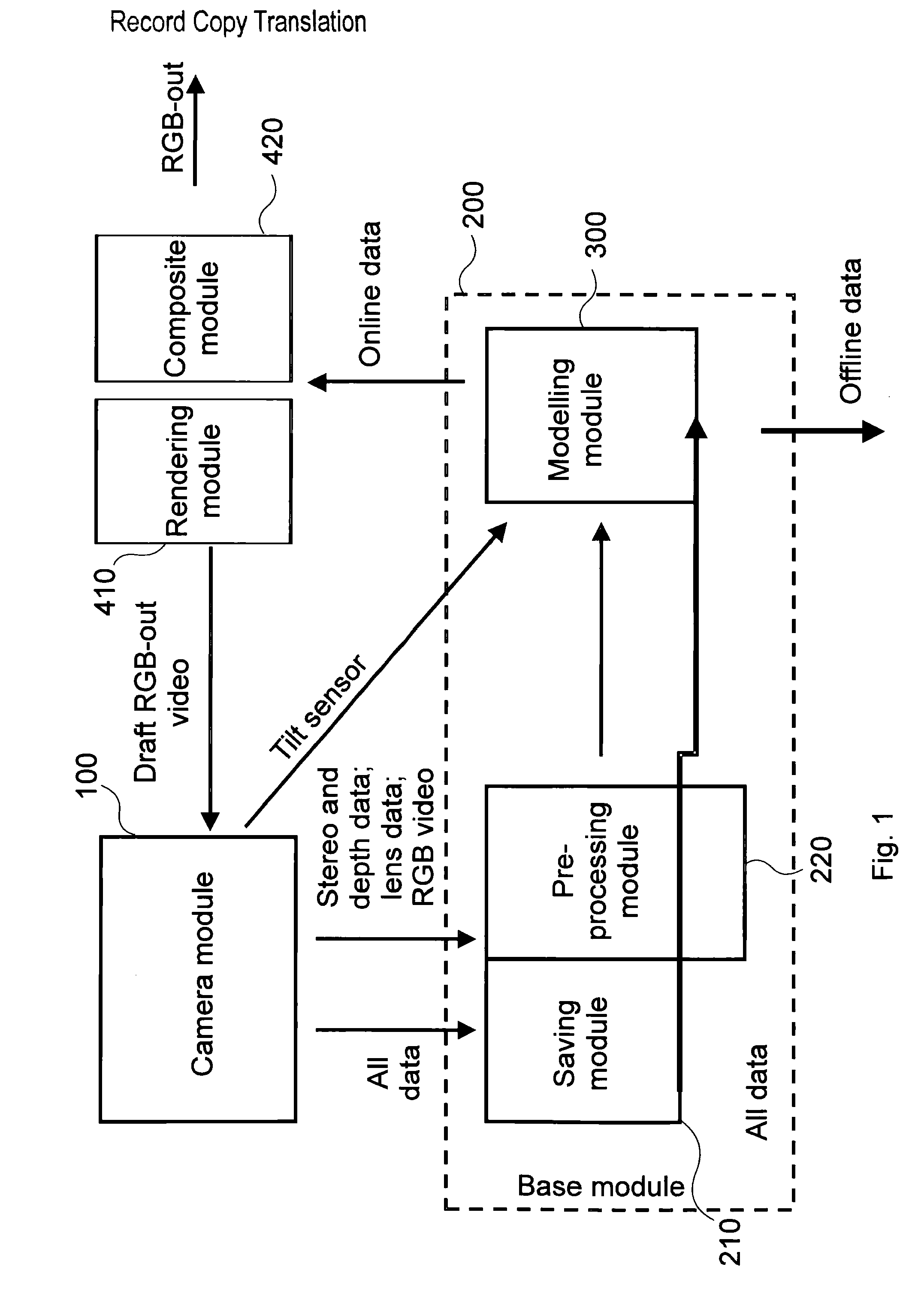
The invention is a system for generating a dynamic three-dimensional model of a space, comprising a camera module (100) comprising an optical sensor adapted for recording image information of the space, and a depth sensor adapted for recording depth information of the space, and a modelling module (300) adapted for generating a dynamic three-dimensional model of the space on the basis of the image information and the depth information. In the system according to the invention the image information with the optical sensor and the depth information with the depth sensor are recorded at a plurality of discrete times. The system according to the invention comprises a synchronisation signal generating module determining synchronised with each other the discrete times associated with the image information and the discrete times associated with the depth information. In the system according to the invention the dynamic three-dimensional model is generated at a plurality of the discrete times of the image information and of the depth information, and at each of the discrete times the image information and the depth information associated with the given discrete time are integrated into the dynamic three-dimensional model on the basis of position and orientation of the camera module (100) at the given discrete time, which position and orientation are determined by the modelling module (300) on the basis of information provided by the sensors of the camera module (100) at the discrete times in an observation window. The invention is, furthermore, a method for generating a dynamic three-dimensional model of a space. (FIG. 1)

Description

TECHNICAL FIELD[0001]The invention relates to a system and method for generating a dynamic three-dimensional model.BACKGROUND ART[0002]Currently, 3D modelling and the application of full or partial CGI (Computer Generated Imagery) objects, and furthermore that of various 3D effects gain increasing popularity in all areas of film making. The procedure usually applied in the film industry is the subsequent supplementing, even with 3D objects, of the film material recorded on location, and the use of image manipulation techniques, for which the 3D modelling of the real environment, and in this regard the knowing of the current position and viewing direction of the original recording camera are necessary. These procedures are supported by several products on the market, but they have a limited use and / or are very expensive.[0003]Nowadays, the film industry increasingly develops in the direction of actively using the data and structure of the space (environment). The already available ap...

Claims


Application Information

Patent Timeline
Patent Type & Authority Applications(United States)
IPC IPC(8): G06T17/00H04N13/02H04N13/239
CPCG06T17/00H04N13/0271G06T2219/024H04N13/0282G06T2219/2004H04N13/0296G06T19/006H04N13/239H04N13/25H04N13/271H04N13/296
Inventor KOMENCZI, NORBERTOROSZI, BALAZSSOOS, GERGELY BALAZS
Owner ZINEMATH ZRT
Learn More