Recording apparatus and setting method
- Summary
- Abstract
- Description
- Claims
- Application Information
AI Technical Summary
Benefits of technology
Problems solved by technology
Method used
Image

Examples
first embodiment
FIGS. 1 and 2
[0033]Firstly, a recording apparatus according to a first embodiment of the invention will be described.
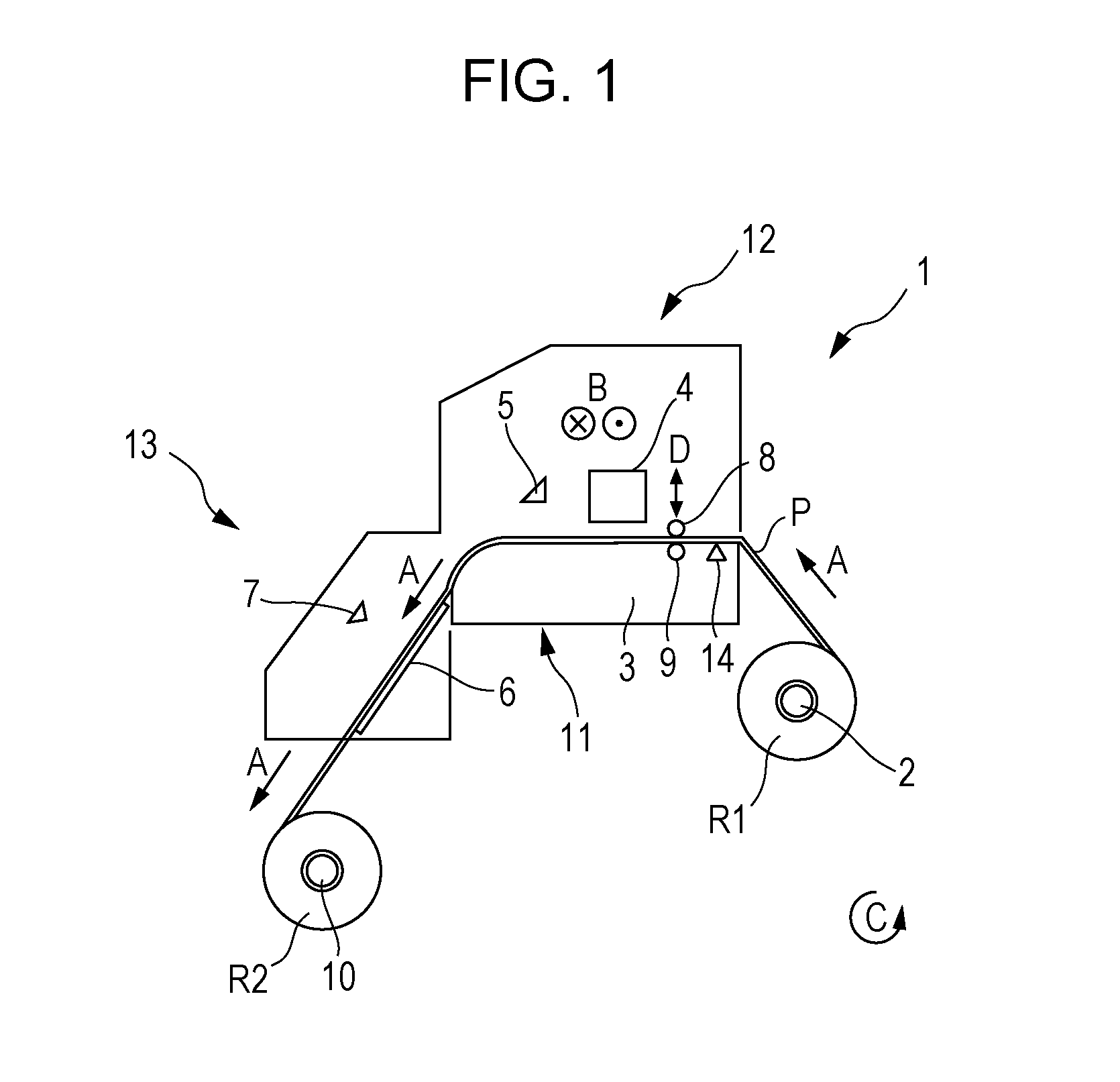
[0034]FIG. 1 is a schematic side view illustrating a recording apparatus 1 according to the embodiment.
[0035]The recording apparatus 1 of the embodiment includes a support shaft 2 that supports a roll R1 of a roll-shaped recording medium P on which the recording is performed. Then, in the recording apparatus 1 of the embodiment, when transporting the recording medium P in a transportation direction A, the support shaft 2 is rotated in a rotating direction C by driving a motor 15 (see FIG. 2) to be rotated. Moreover, in the embodiment, the roll-type recording medium P that is wound such that a recording surface is on the outside is used, but if a roll-type recording medium P that is wound such that a recording surface is on the inside is used, it is possible to feed the roll R1 in a direction reverse to the rotating direction C of the support shaft 2.
[0036]Furthermore,...
second embodiment
FIG. 3
[0064]Next, a recording apparatus of a second embodiment will be described with reference to the accompanying drawing.
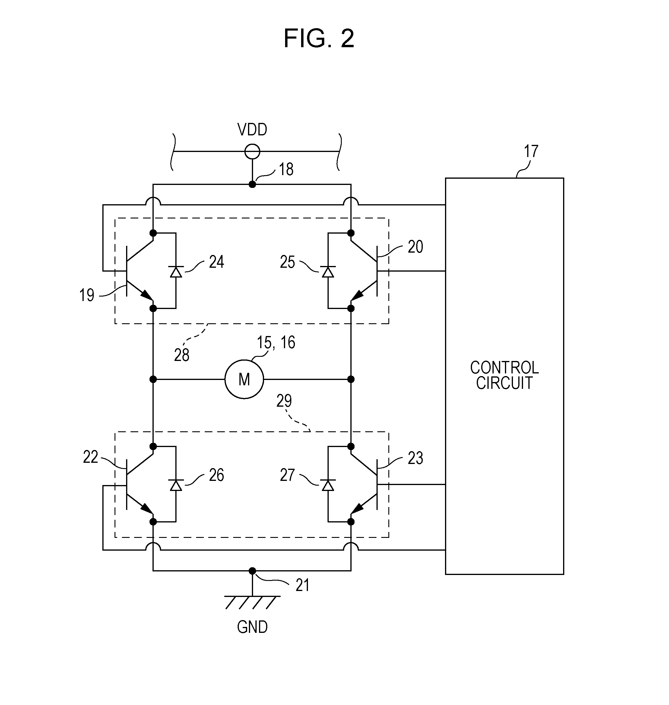
[0065]FIG. 3 is a diagram of a motor driving circuit of the recording apparatus 1 according to the second embodiment. Moreover, the same reference numerals are given to configuration members in common with the above embodiment and detailed description will be omitted.
[0066]Moreover, the recording apparatus 1 of the embodiment has the same configuration as the recording apparatus 1 of the first embodiment except that a counter electromotive force detection section 30 is provided. Furthermore, similar to the recording apparatus 1 of the first embodiment, in the recording apparatus 1 of the embodiment, a diagram of a motor driving circuit of a winding motor 16 which drives the winding shaft 10 also has the same configuration as that of the diagram of the motor driving circuit of the motor 15. Thus, the following description also serves as description of the motor ...
embodiment
of Setting Method of Recording Medium P (FIG. 4)
[0070]Next, a setting method of the recording medium P of the embodiment will be described.
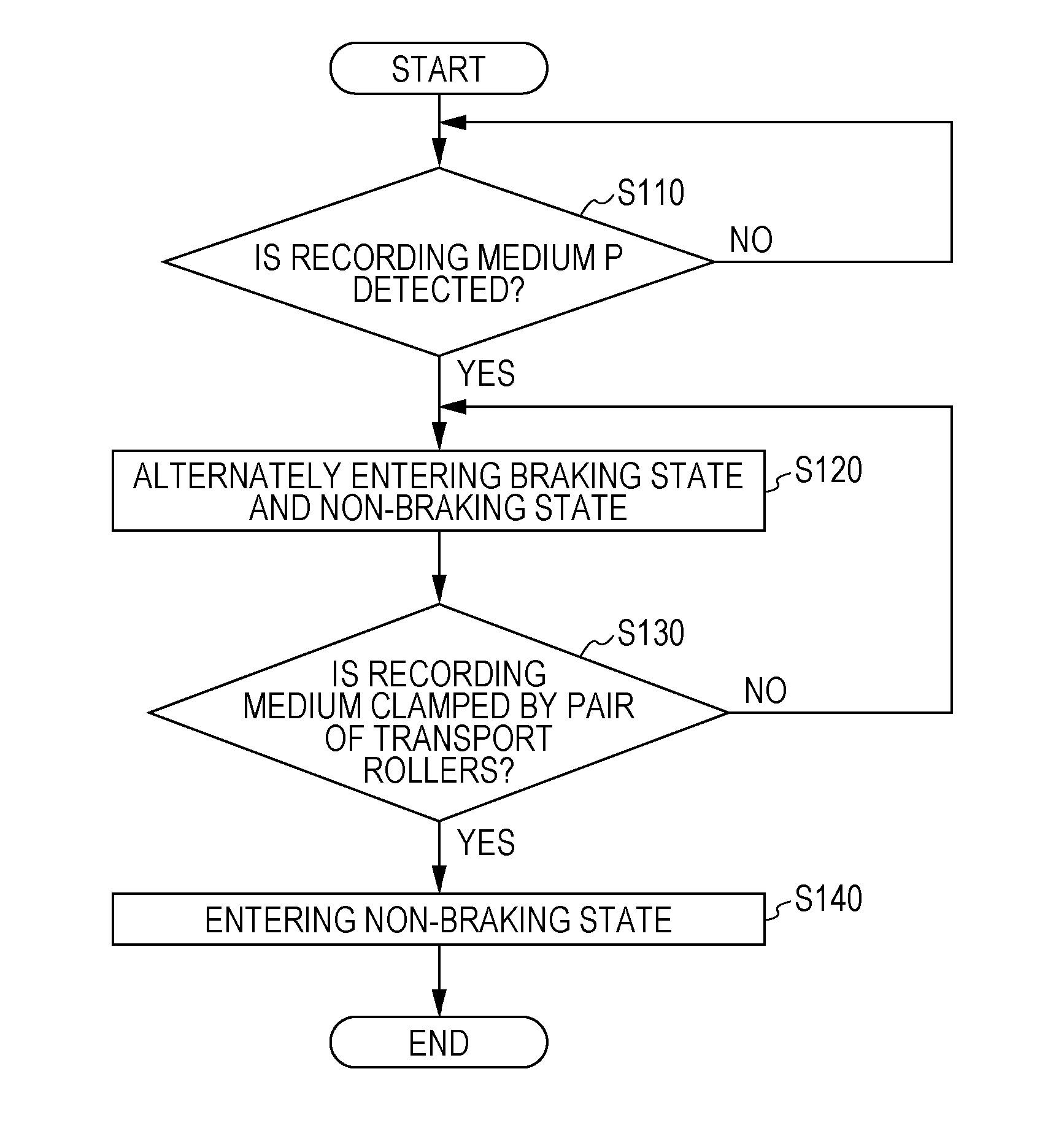
[0071]FIG. 4 is a flowchart illustrating a setting method of the recording medium P of the embodiment.
[0072]Moreover, the setting method of the recording medium P of the embodiment is an embodiment that is performed by using the recording apparatus 1 of the first embodiment. On the other hand, if the setting method is performed by using the recording apparatus 1 of the second embodiment, it is determined whether or not the counter electromotive force detection section 30 detects the counter electromotive force of a predetermined threshold or greater before executing step S120 described below, and if the counter electromotive force of the threshold or more is detected, step S120 may be executed.
[0073]In the setting method of the recording medium P of the embodiment, if the recording medium P is mounted on the support shaft 2 by the user and introd...
PUM
 Abstract
Description
Claims
Application Information
 - R&D
- Intellectual Property
- Life Sciences
- Materials
- Tech Scout
- Unparalleled Data Quality
- Higher Quality Content
- 60% Fewer Hallucinations
Browse by: Latest US Patents, China's latest patents, Technical Efficacy Thesaurus, Application Domain, Technology Topic, Popular Technical Reports.
© 2025 PatSnap. All rights reserved.Legal|Privacy policy|Modern Slavery Act Transparency Statement|Sitemap|About US| Contact US: help@patsnap.com