
Wireless transceiver with circulator and active cancellation and methods for use therewith

a wireless transceiver and circulator technology, applied in the direction of radio transmission, transmission control/equalisation, electric devices, etc., can solve the problems of adversely affecting the processing of received signals at the cost of multiple tx filters and duplexers,

Inactive Publication Date: 2015-05-28
AVAGO TECH INT SALES PTE LTD
View PDF8 Cites 26 Cited by
  • Summary
  • Abstract
  • Description
  • Claims
  • Application Information

AI Technical Summary

Benefits of technology

The patent text describes a wireless communication system that includes a plurality of base stations and access points. The system uses multiple frequency bands to support wireless communications. However, the use of multiple frequency bands can lead to interference between the transmitted signals and the received signals. The patent proposes a solution to reduce this interference by using narrow band filters and duplexers in the transmit circuitry of the wireless communication device. The patent also discusses the issue of cross coupling between antennas and proposes various methods to reduce this interference. Overall, the patent aims to improve the quality and efficiency of wireless communication systems.

Problems solved by technology

A wireless communication device operating in full, or near full, duplex mode may have the transmitted signal leak (i.e., TX bleed-through) into the receive circuitry of the device via the circuitry within the wireless communication device, which adversely effects processing received signals.
While this does reduce TX bleed-through, it does so at the cost of multiple TX filters and duplexers (e.g., one set per frequency of use).
In addition, a wireless communication device operating in full, or near full, duplex mode may have the transmitted signal reflected into the receive circuitry via conditions outside of the wireless communication device, which also adversely effects processing received signals.

Method used


Image

  • Wireless transceiver with circulator and active cancellation and methods for use therewith
  • Wireless transceiver with circulator and active cancellation and methods for use therewith
  • Wireless transceiver with circulator and active cancellation and methods for use therewith

Examples


Embodiment Construction

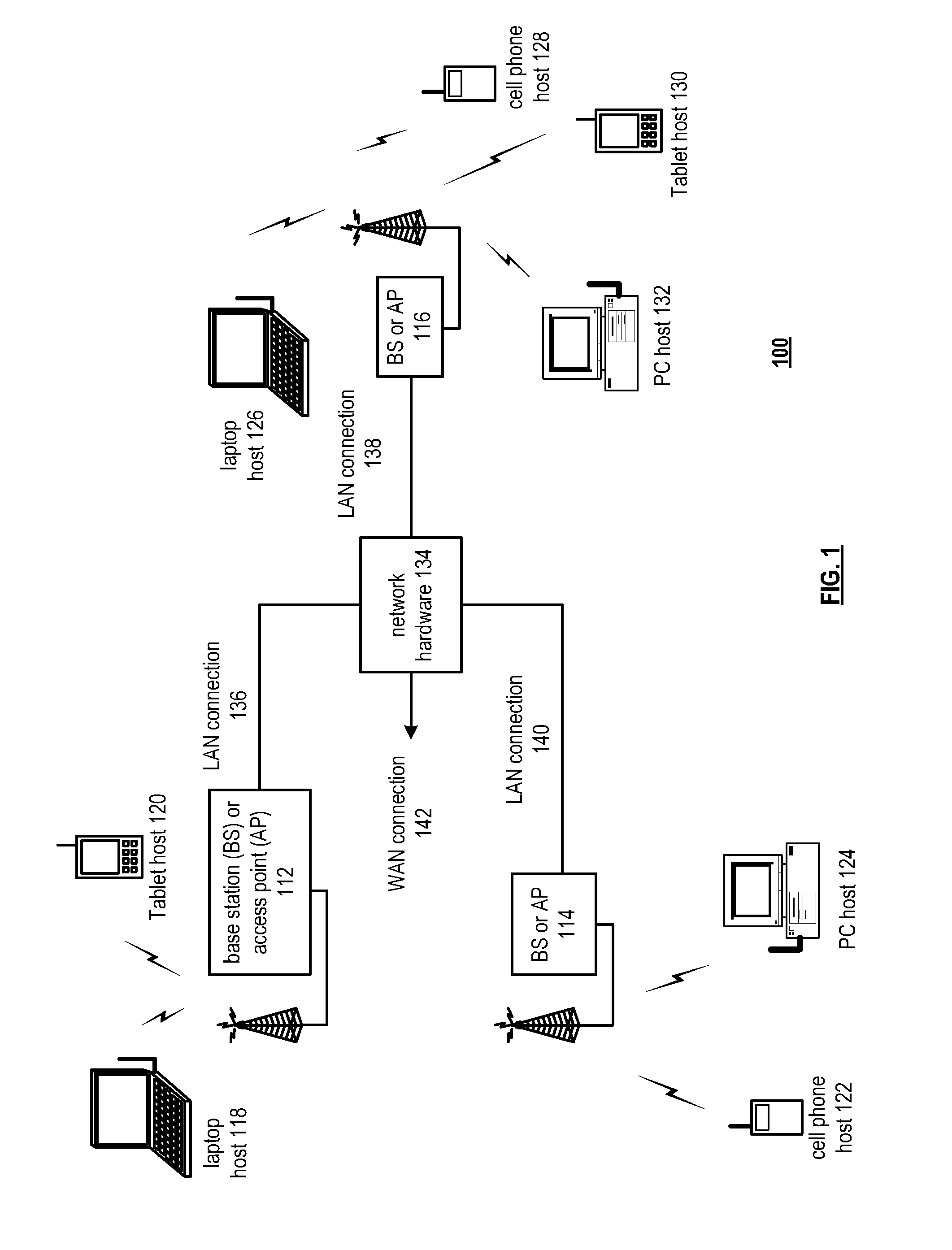
[0024]FIG. 1 is a schematic block diagram of a wireless communication system in accordance with various embodiments. A communication system 100 includes a plurality of base stations and / or access points 112, 114 and 116, a plurality of wireless communication devices 118, 120, 122, 124, 126, 128, 130 and 132 and a network hardware component 134. The wireless communication devices 118, 120, 122, 124, 126, 128, 130 and 132 may be laptop host computers 118 and 116, tablet hosts 120 and 130, personal computer hosts 124 and 132, cellular telephone hosts 122 and 128 and / or other wireless devices.

[0025]The base stations or access points 112, 114 and 116 are operably coupled to the network hardware 134 via local area network connections 136, 138 and 140. The network hardware 134, which may be a router, switch, bridge, modem, system controller, etcetera, provides a wide area network connection 142 for the communication system 100. Each of the base stations or access points 112, 114 and 116 ha...


PUM


Abstract

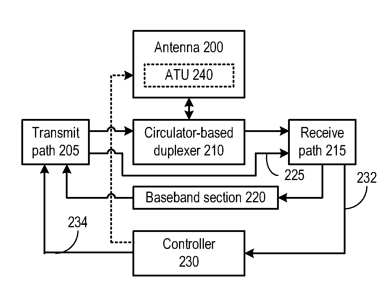
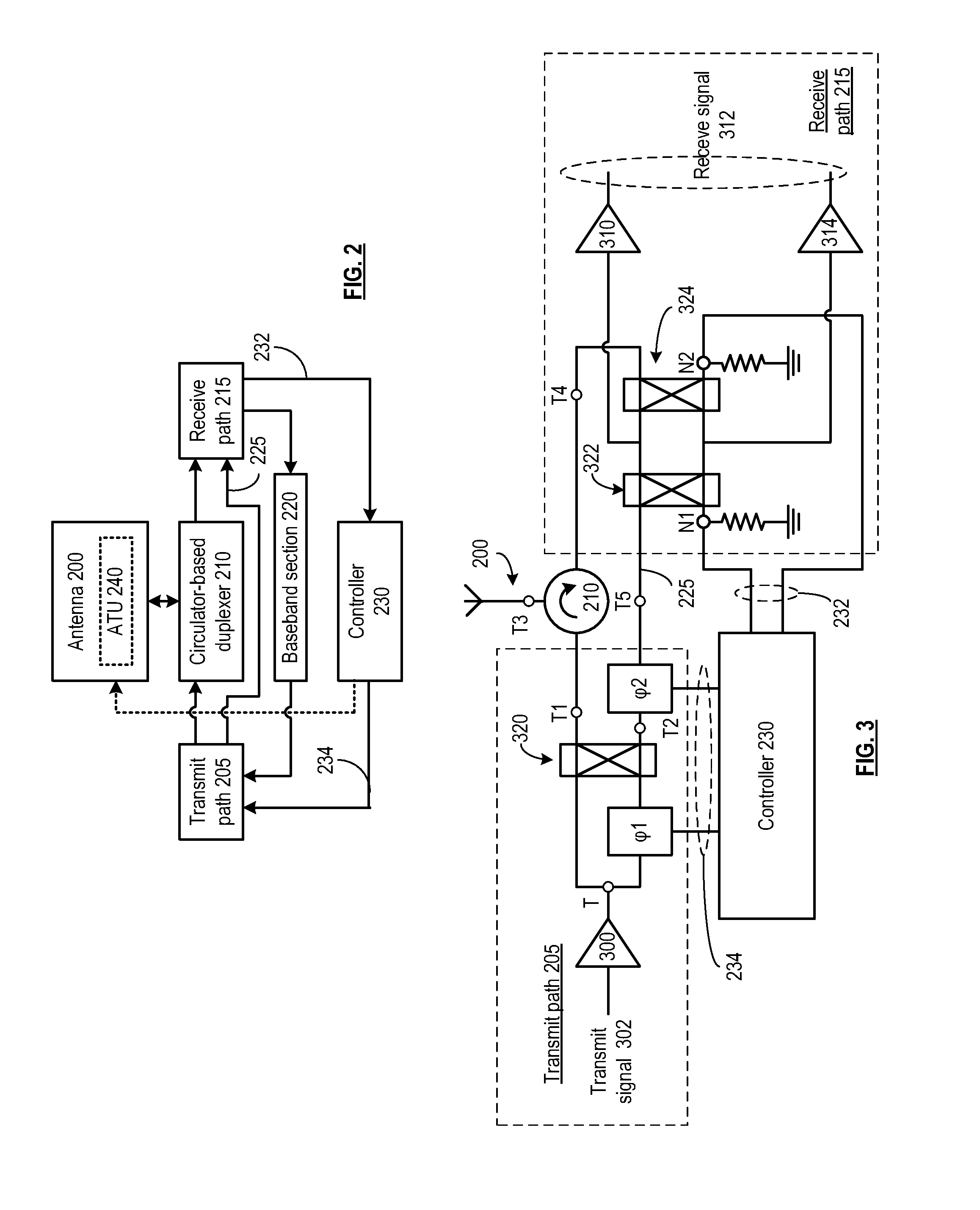
A wireless transceiver includes a transmit path configured to generate a radio frequency (RF) transmit signal for transmission via an antenna, the transmit path generating a feedforward signal having at least one adjustable phase. A receive path is configured to receive an RF receive signal via the antenna. A circulator-based duplexer includes a circulator configured to couple the transmit signal from the transmit path to the antenna and to couple the receive signal from the antenna to the receive path. A controller is configured to process feedback from the receive path and to control the at least one adjustable phase to cancel portions of the transmit signal on the receive path.

Description

CROSS-REFERENCE TO RELATED APPLICATIONS[0001]This application claims priority under 35 U.S.C. 119 to the provisionally filed application entitled, HIGH ISOLATION RADIO FRONT END AND APPLICATIONS THEREOF, having application Ser. No. 61 / 909,792 and filed on Nov. 27, 2013, the contents of which are incorporated herein by reference for any and all purposes.STATEMENT REGARDING FEDERALLY SPONSORED RESEARCH OR DEVELOPMENT—NOT APPLICABLEINCORPORATION-BY-REFERENCE OF MATERIAL SUBMITTED ON A COMPACT DISC—NOT APPLICABLEBACKGROUND[0002]1. Technical Field[0003]This disclosure relates generally to wireless communication systems and to wireless communication devices that operate therewith.[0004]2. Description of Related Art[0005]In many wireless communication systems, wireless communications occur in a full duplex manner (e.g., transmit and receive on the same frequency) or a near full duplex manner (e.g., transmit and receive on different, but very close, frequencies). In addition, many of the sy...

Claims


Application Information

Patent Timeline
Patent Type & Authority Applications(United States)
IPC IPC(8): H04B1/52
CPCH04B1/525H04B1/0458H04B1/18
Inventor YOON, SEUNGHWANROFOUGARAN, AHMADREZATARIGHAT MEHRABANI, ALIREZA
Owner AVAGO TECH INT SALES PTE LTD
Learn More