
Orthopaedic bone depth gauge and method

a technology of depth gauge and orthopaedic surgery, which is applied in the field of orthopaedic surgery art, can solve the problems of adding significantly to the assembly cost, being too expensive to discard, and existing depth gauges used in re-sterilizable trays used in the operating room, and achieves the effect of cost-effectiveness

Active Publication Date: 2015-05-14
BIOMET MFG CORP
View PDF12 Cites 12 Cited by
  • Summary
  • Abstract
  • Description
  • Claims
  • Application Information

AI Technical Summary

Benefits of technology

The present invention provides a cost-effective bone depth gauge that can be used once and then thrown away. The gauge includes a thin metal tip with a hook at the end, which is connected to a handle through a tubular element. The tip is made using a process called photo chemical machining, and the whole product can be made using standard manufacturing methods. The invention also includes a method for making the tip. This tool is useful for orthopaedic surgeons who need to measure the depth of bones they are cutting or drilling.

Problems solved by technology

Existing depth gauges used in re-sterilizable trays used for the operating room are usually far too expensive to discard after each use and are usually consigned to a hospital or surgical center.
The tip is typically manufactured from a rod of steel and adds significantly to the cost of the assembly.

Method used


Image

  • Orthopaedic bone depth gauge and method
  • Orthopaedic bone depth gauge and method
  • Orthopaedic bone depth gauge and method

Examples


Embodiment Construction

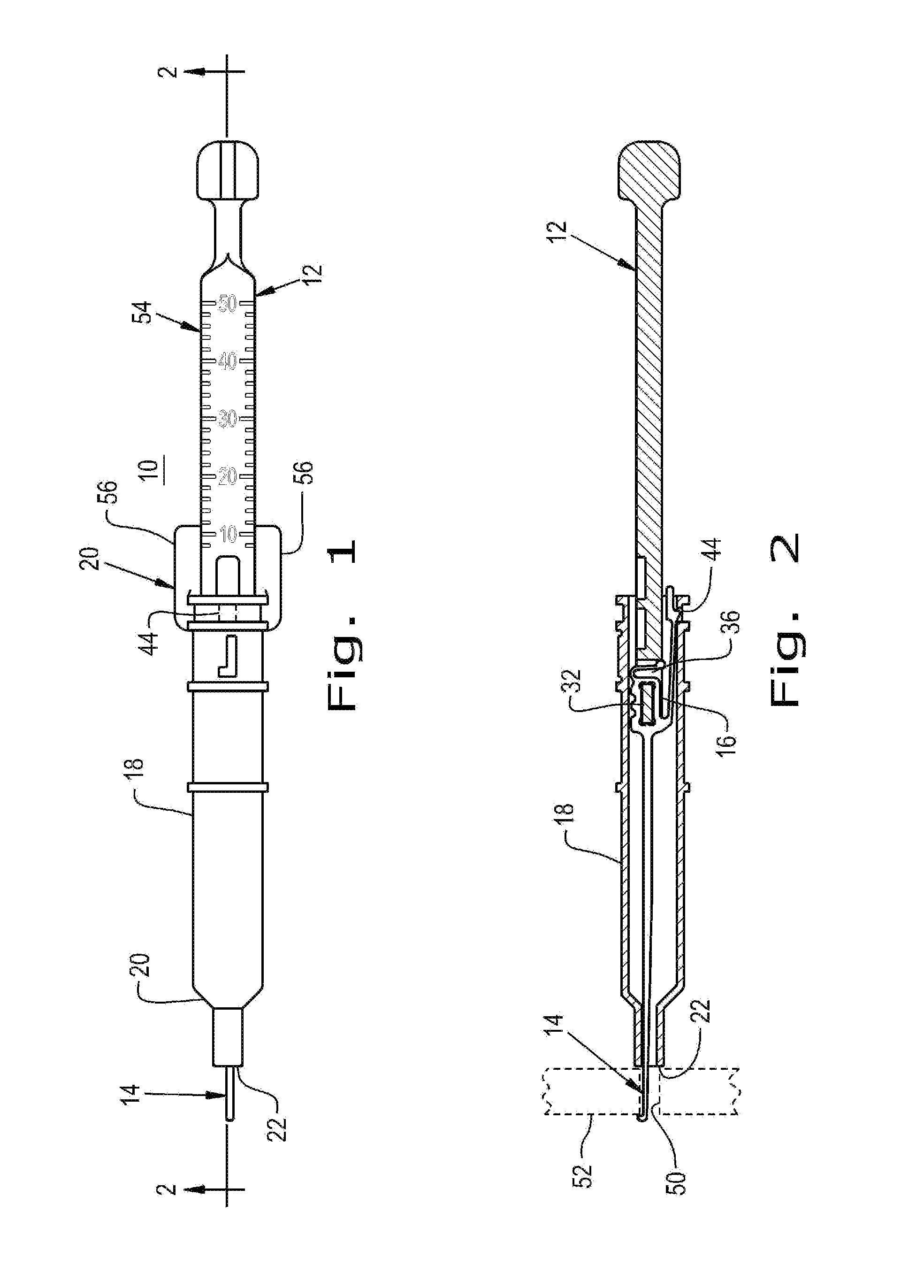
[0018]FIG. 1 shows an orthopaedic bone depth gauge 10 which includes a proximal handle 12 providing a mounting for a tip 14 on the distal end 16 of handle 12. A tubular element 18 is telescoped over the assembly and has a proximal end 20 over handle 12 and a distal end 22 over tip 14.

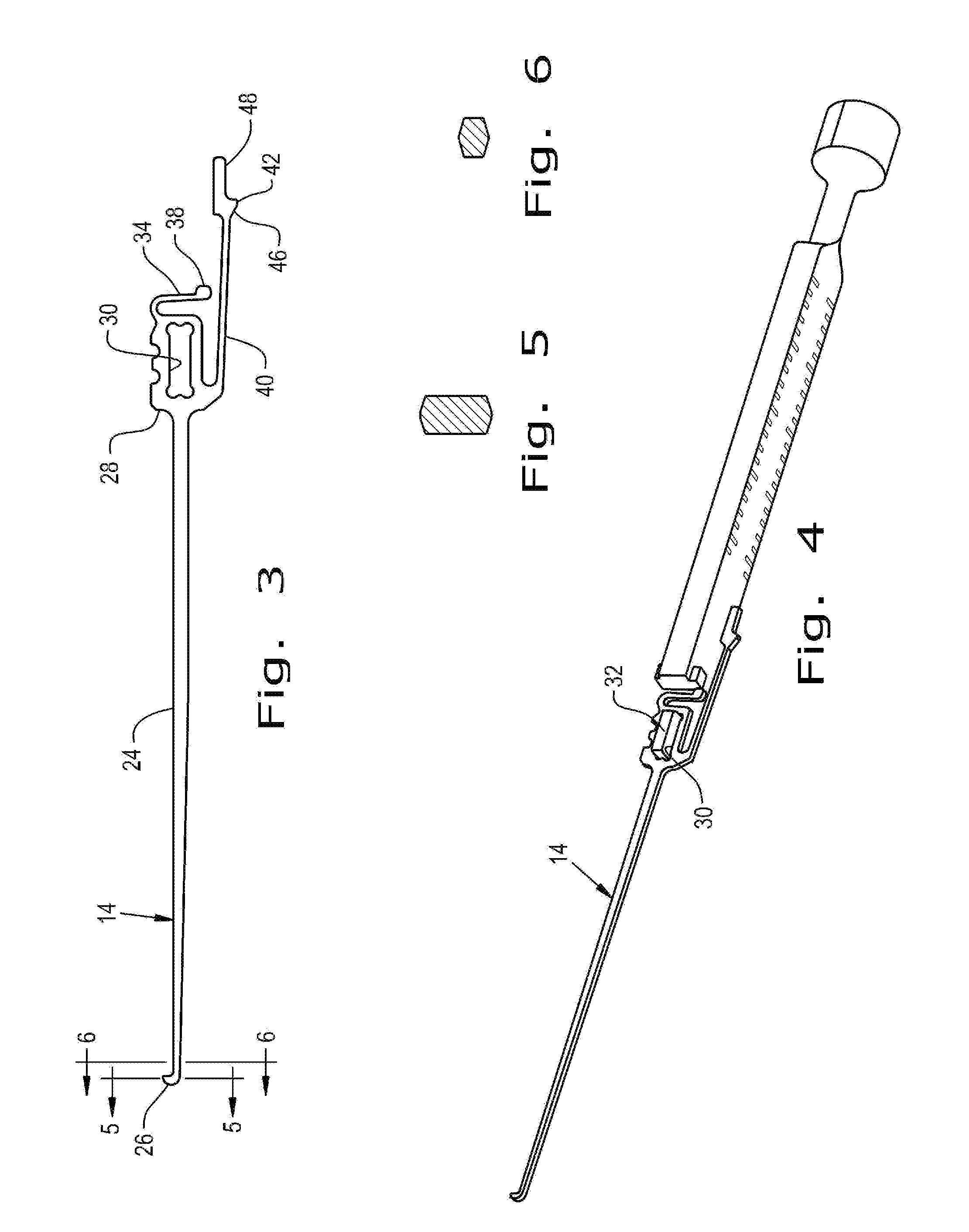
[0019]Referring now to FIG. 3, tip 14 is made of thin metal sheet up to around 1 mm in thickness, preferably up to 1.07 mm thickness). The configuration illustrated in FIG. 3 is a final configuration before assembly with the handle 12 and tubular element 18. Tip 14 has an elongated shaft 24 terminating in a hook 26 at its distal end. At the proximal end 28 there is a window 30 sized and configured to be received over a post 32 integral with handle 12. A tab 34 is coplanar with the tip 14 and has a flexible section configured to be received in a notch 36 on handle 12. A tab 38, integral with tab 34, permits an operator to depress tab 34 sufficiently to clear notch 36 and remove tip 14 laterally from post...


PUM

PropertyMeasurementUnit
thicknessaaaaaaaaaa
thicknessaaaaaaaaaa
depthaaaaaaaaaa

Abstract

A bone depth gauge having a distal handle to which a tip is releasably connected. The tip is formed by photochemical machining to produce a tip and hook on the distal end with an approximate hexagonal cross section. The manufacturing costs of the tip are low enough to provide it in a one use package. A tubular element is releasably telescoped over the tip and handle to enable determination of the depth of a hole formed in a bone.

Description

BACKGROUND OF THE INVENTION[0001]1. Field of the Invention[0002]The present invention relates to the orthopaedic surgery art and more specifically to bone depth gauges.[0003]2. Description of the Related Art[0004]Installation of orthopaedic trauma reconstruction plates frequently require that holes be drilled through bones to allow the installation of screws that are used to restore the patient's natural anatomy. The depth of each hole must be measured so that the correct screw may be chosen to attach a support plate to the bone. Existing depth gauges used in re-sterilizable trays used for the operating room are usually far too expensive to discard after each use and are usually consigned to a hospital or surgical center. They are expected to be reused indefinitely.[0005]Devices of this type, because of the long expected use, are typically machined, stainless steel or anodized aluminum with a stainless steel tip hook. This style of depth gauge has a hook that extends from the distal...

Claims


Application Information

Patent Timeline
Patent Type & Authority Applications(United States)
IPC IPC(8): A61B19/00B65B55/16
CPCB65B55/16A61B19/46A61B90/06A61B2090/061
Inventor KORTENBACH, JUERGEN
Owner BIOMET MFG CORP
Learn More