
Ergonomic, lighted uterine manipulator with cautery

a lighted, uterine technology, applied in the field of ergonomic uterine manipulators, can solve the problems of inability to provide ergonomic handles to enable surgical control of specimens, premature abandonment of patents, and difficulty in routine implementation of distal cups and attached cervixes by operating room staff, so as to facilitate benefits and convenience, enhance uterine manipulation, and identify cervical cup edges and targeted fornices. the effect of easy identification

Active Publication Date: 2015-05-07
LSI SOLUTIONS
View PDF5 Cites 13 Cited by
  • Summary
  • Abstract
  • Description
  • Claims
  • Application Information

AI Technical Summary

Benefits of technology

This patent describes a new technology for surgical procedures that can be used safely and easily by surgeons. The technology includes a cervical engagement device with a custom co-axial handle, an angled shaft, and a sliding flexible vaginal occluder to secure the shaft. The cervical engagement device can be rotated to pivot the uterus in the direction of the indicator ridge, allowing for easier identification and dissection of the uterus. The technology also includes a vaginal illuminator for transillumination light delivery through the distal cervical cup. Overall, this technology simplifies and enhances critical anatomy identification and tissue manipulation in routine and complex minimally invasive gynecologic surgical interventions.

Problems solved by technology

Further, it failed to provide an ergonomic handle to enable surgical control of the specimen.
This patent appears to have never led to a commercially available product and the patent was prematurely abandoned.
This means of moving the distal cup along with the attached cervix has proved to be surprisingly difficult for operating room staff routine implementation.
Through limitations in effectiveness and ergonomics, none of these previous alternatives truly satisfy the requisite functionality of an optimized uterine manipulator for minimally invasive surgery.
Gynecologic surgeons have repeatedly reported that remote uterine dissection, especially the vaginal cuff separation, remains a significant challenge despite multiple currently available products from other companies.
Even with the availability and use of earlier uterine manipulator products, difficulties with cervical and uterine dissections are frequently associated with iatrogenic injuries to patients' bladders, ureters, vaginal vaults and surrounding tissues.
Difficulties with this dissection often add substantial time to these operative procedures and are one of the leading causes of the need to convert laparoscopic procedures to more invasive open laparotomies.
Since known alternative designs provide their uterine insertion elements already attached to the rest of their device, their distal insertion means is burdened with obstructing elements, such as their preinstalled balloons and cervical cups.
Non-separated insertion features make device installation difficult to visualize and perform.
The transvaginal installation of alternative products is significantly encumbered by having their devices' distal insertion components with unnecessary pre-attached larger diameter features.
By creating further distance between these blood vessels and the adjacent ureter, this simple technique of rotating the coaxial handle to displace the uterus reduces the potential risk of ureteral injury during dissection.
When using commercially available alternative uterine manipulation products, it is frequently difficult to localize the vaginal fornices during laparoscopic hysterectomy.

Method used


Image

  • Ergonomic, lighted uterine manipulator with cautery
  • Ergonomic, lighted uterine manipulator with cautery
  • Ergonomic, lighted uterine manipulator with cautery

Examples


Embodiment Construction

[0051]While the invention has been described in connection with certain presently preferred embodiments thereof, those skilled in the art will recognize that many modifications and changes may be made without departing from the broad scope of the invention, which is intended to be defined solely by the appended claims.

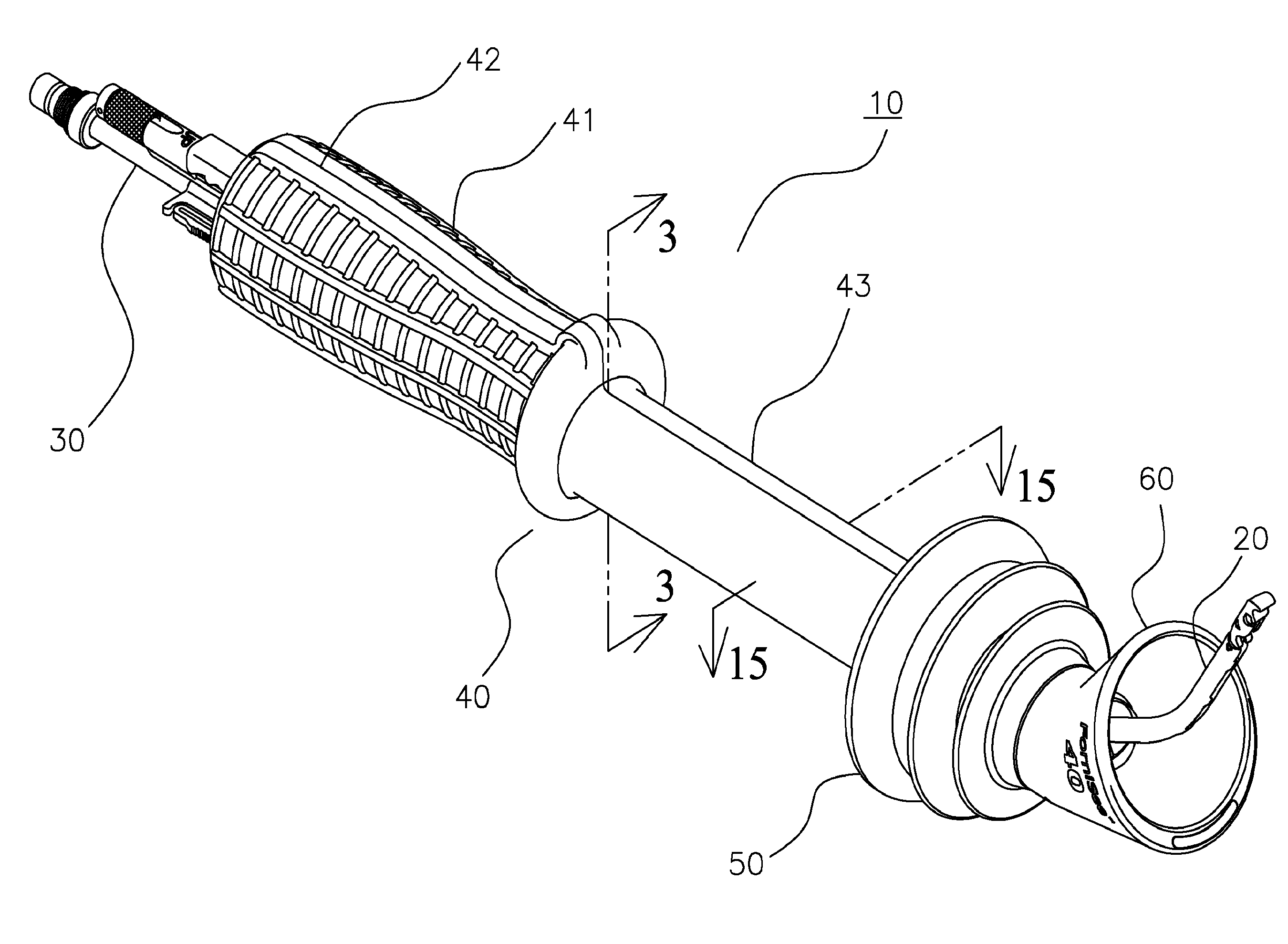
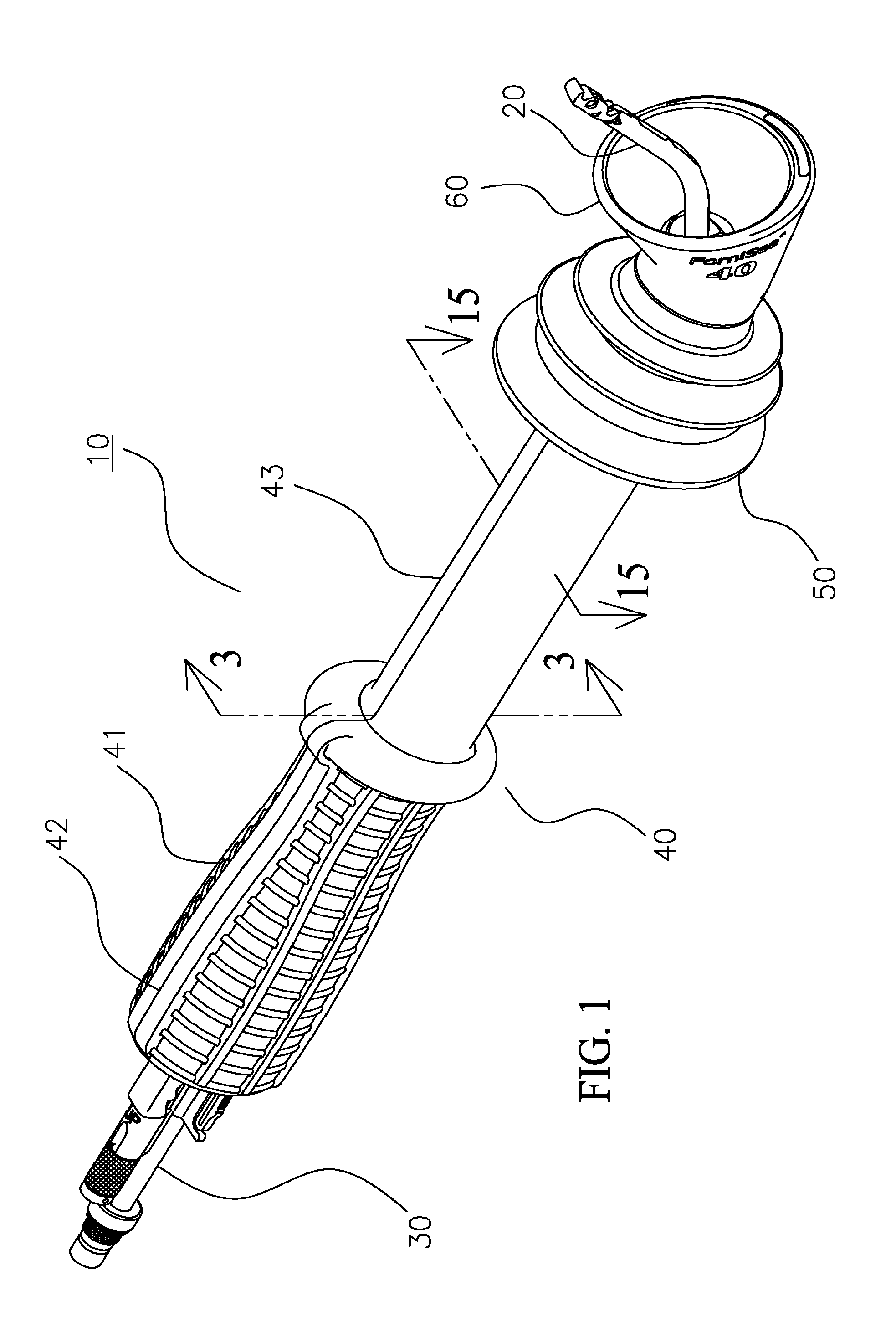
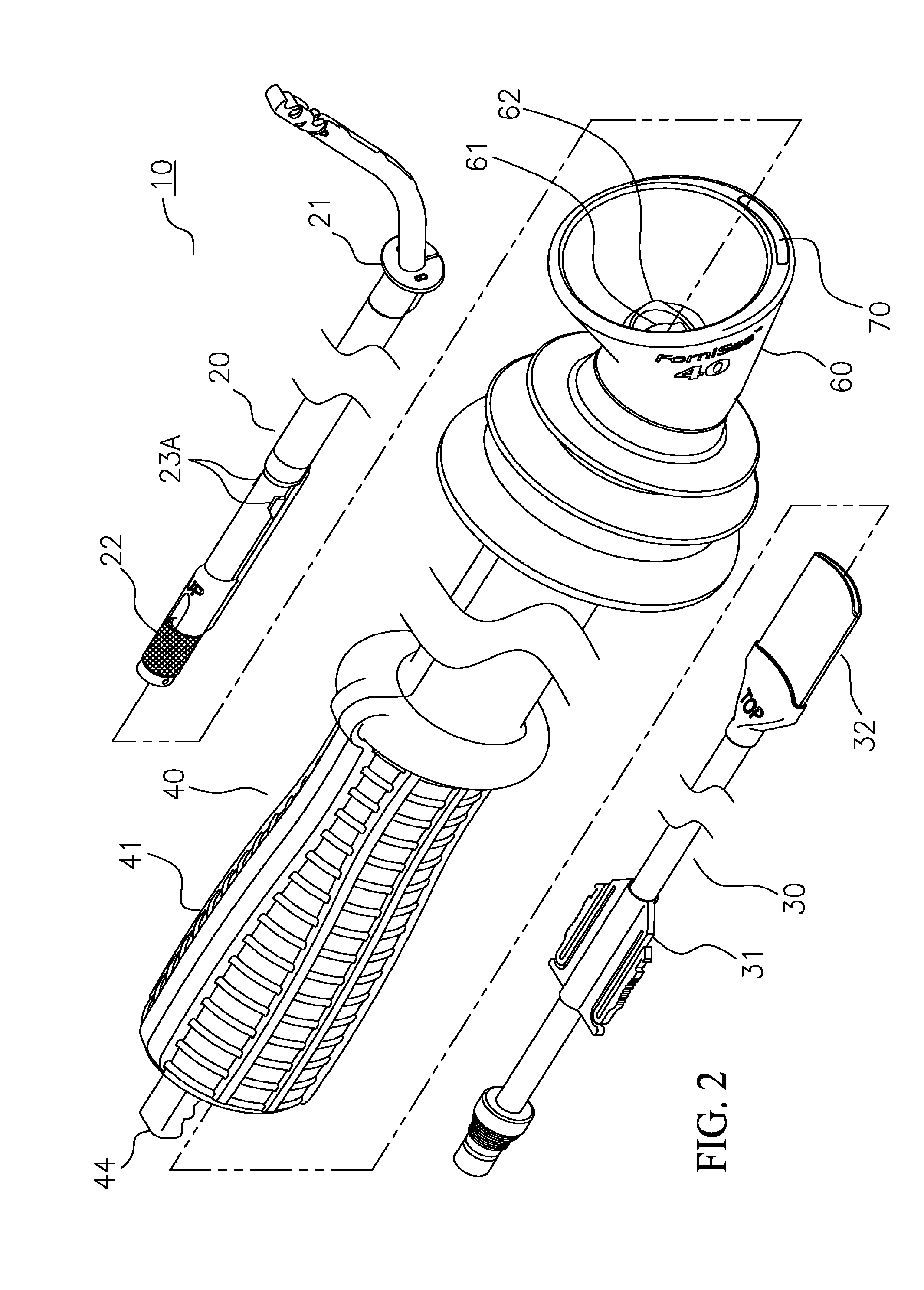
[0052]Referring to FIG. 1, a perspective view of a uterine manipulator 10 is shown, comprised of a sound 20 and a light wand 30 accepted within and housed by a device 40. The sound 20 and light wand 30 are generally manufactured such that they are reusable and preferably comprised of rigid, sterilizable, and cleanable materials such as stainless steels and the like. The device 40 is typically disposable and generally comprised of sterilizable molded polymers.

[0053]Evident in the device 40 are a proximally located textured handle 41 imparting a tactile surface for ease of physical manipulation of manipulator 10 and device 40, an indicator ridge 42 to delineate manipulat...


PUM


Abstract

A uterine manipulator includes a sound and a body. The sound has a selectively actuatable anchor disposed proximate a distal end and an operating mechanism spaced from the anchor for controlling actuation of the anchor. The body has a passage therethrough adapted to receive the sound passed proximally through the body to a position in which the operating mechanism is accessible proximally of the body and the anchor extends distally.

Description

CROSS-REFERENCE TO RELATED APPLICATIONS[0001]This application is a continuation of co-pending U.S. patent application Ser. No. 13 / 165,494, entitled “ERGONOMIC, LIGHTED UTERINE MANIPULATOR WITH CAUTERY”, filed on Jun. 21, 2011. As such, this application claims the benefit of the Jun. 21, 2011 filing date.BACKGROUND[0002]Despite decades of commercial availability of a wide variety of transvaginally placed uterine manipulators, the need still exists for more effective and ergonomic surgical instruments to optimize the remote manipulation of a patient's vaginal, cervical and uterine tissues during modern minimally invasive gynecologic procedures. Naturally occurring openings in the body, like the vagina, urethra, anus and mouth, provide places to engage internal tissues without the requirement of cutting a hole in the patient's skin. Utilization of the vaginal canal to surgically access the cervix and uterus is routinely part of modern health care. As major gynecologic therapeutic inter...

Claims


Application Information

Patent Timeline
IPC IPC(8): A61B17/42A61B18/04A61B19/00
CPCA61B17/4241A61B2018/00595A61B18/04A61B19/5202A61B18/1485A61B90/30A61B2017/00455A61B2018/00559A61B2090/306
Inventor SAUER, JUDE S.
Owner LSI SOLUTIONS
Learn More