
Rotary wing aircraft having two main engines together with a less powerful secondary engine, and a corresponding method

a technology of secondary engine and rotary wing aircraft, which is applied in the direction of combination engines, machines/engines, transportation and packaging, etc., can solve the problems of reducing the specific fuel and reducing the specific consumption of a given turboshaft engine. achieve the effect of sufficient electricity and non-negligible weight saving

Active Publication Date: 2015-05-07
EUROCOPTER
View PDF21 Cites 15 Cited by
  • Summary
  • Abstract
  • Description
  • Claims
  • Application Information

AI Technical Summary

Benefits of technology

This patent describes an aircraft that has a control system to use two turboshaft engines for better performance. The main engine operates throughout the flight while the secondary engine is used during specific stages of flight. The secondary engine provides extra power to avoid using the main engines at their maximum capacity. This results in better performance and efficiency of the aircraft.

Problems solved by technology

However, the auxiliary power unit does not drive a rotor main gearbox on a rotary wing aircraft.
It is also observed that the greater the power of a turboshaft engine, the lower its specific fuel consumption.
Nevertheless, the specific consumption of a given turboshaft engine also varies as a function of the power it delivers.
Consequently, a turboshaft engine presents specific consumption that is optimized when the turboshaft engine is developing the maximum power authorized for that turboshaft engine.
Specifically, when the power it develops becomes lower, the specific consumption of the engine increases.
It can be seen from the above observations that it can be difficult to dimension a turboshaft engine.
When it is found that the power from a single turboshaft engine is not sufficient, manufacturers naturally install a plurality of turboshaft engines on their aircraft.
Nevertheless, the use of such multi-engined aircraft raises the problem of safety in flight in the event of an engine failing.
In application of the above-mentioned principles, the specific consumption of turboshaft engines while they are using the maximum continuous power MCP is thus not optimized, since the maximum continuous power MCP is very different from the maximum power that the engine can deliver.
The weight of the engine is then reduced, but that has the consequence of reducing its maximum continuous power MCP.
However, the use of turboshaft engines that are less powerful compared with a twin-engined aircraft is not fully optimized.
The dimensioning of the power plant of an aircraft is thus complex, independently of the configuration that is selected.

Method used


Image

  • Rotary wing aircraft having two main engines together with a less powerful secondary engine, and a corresponding method
  • Rotary wing aircraft having two main engines together with a less powerful secondary engine, and a corresponding method

Examples


Embodiment Construction

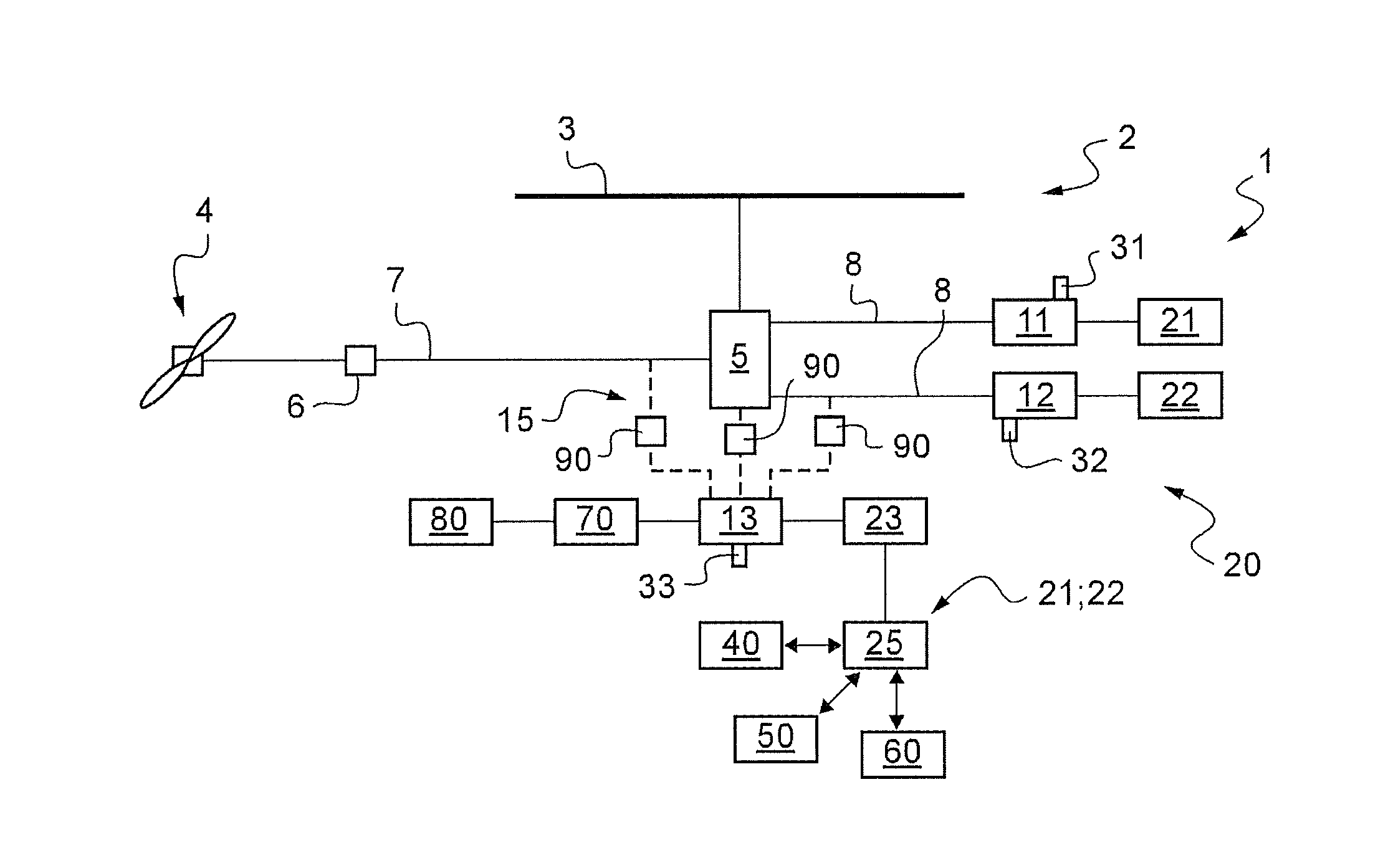
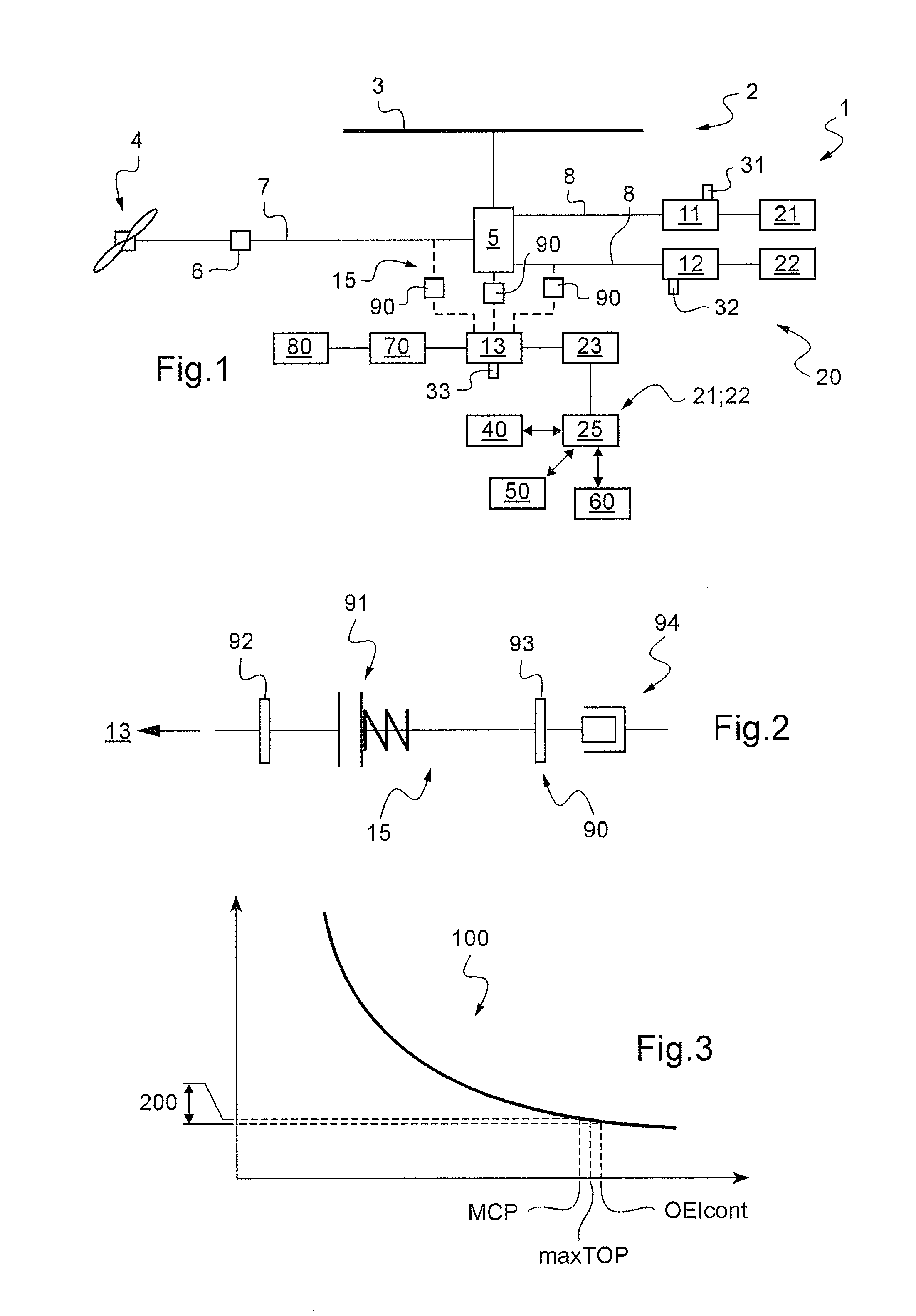
[0157]FIG. 1 shows an aircraft 1 in diagrammatic manner for the purpose of illustrating the invention.

[0158]The aircraft 1 may have a rotary wing 2 comprising at least one rotor 3 for providing lift and possibly also propulsion. In addition, the aircraft may include at least one additional rotor 4 in particular for controlling yaw movement of the aircraft.

[0159]Consequently, the aircraft 1 has a main gearbox “MGB”5 for driving the rotary wing 2 in rotation, and a secondary gearbox 6 for driving the additional rotor 4 in rotation. A power transmission train 7 connects the main gearbox MGB 5 to the secondary gearbox 6.

[0160]In addition, the aircraft has three turboshaft engines 11, 12, and 13 capable of setting the rotary wing 2 and the additional rotor 4 into rotation via the main and secondary gearboxes 5 and 6.

[0161]More precisely, the aircraft 1 is provided in particular with two main turboshaft engines 11 and 12. These two main turboshaft engines 11 and 12 may be connected to the...


PUM


Abstract

An aircraft (1) having a rotary wing (2) and turboshaft engines (11, 12, 13) for driving said rotary wing (2). The aircraft then includes two main engines (11, 12) that are identical, each capable of operating at at least one specific rating associated with a main power (maxTOP, OEIcont), and a secondary engine (13) capable of operating at at least one specific rating by delivering secondary power (maxTOP′, OEIcont′) proportional to the corresponding main power (maxTOP, OEIcont) in application of a coefficient of proportionality (k) less than or equal to 0.5, said aircraft having a control system (20) for driving the rotary wing by causing each main engine (11, 12) to operate continuously throughout a flight, and by using the secondary engine (13) as a supplement during at least one predetermined specific stage of flight.

Description

CROSS REFERENCE TO RELATED APPLICATION[0001]This application claims priority to French patent application No. FR 12 03183 filed on Nov. 26, 2012, the disclosure of which is incorporated in its entirety by reference herein.BACKGROUND OF THE INVENTION[0002](1) Field of the Invention[0003]The present invention relates to a rotary wing aircraft having two main engines together with a secondary engine that is less powerful, and the invention also relates to a method of controlling the aircraft.[0004]The term “turboshaft engine” is used to mean a power unit contributing to the propulsion and / or lift of an aircraft. On an aircraft having a rotary wing, the term “turboshaft engine” is used to designate a power unit that drives rotation of a main gearbox “MGB” that in turn drives rotation of at least one rotor of the rotary wing.[0005](2) Description of Related Art[0006]An aircraft is sometimes fitted with an auxiliary power unit (APU). The auxiliary power unit may for example be used for ge...

Claims


Application Information

Patent Timeline
Patent Type & Authority Applications(United States)
IPC IPC(8): F01D13/00F01D15/12B64C27/12
CPCF01D13/003F01D15/12B64C27/12B64D35/08B64D35/04B64D41/00
Inventor CERTAIN, BERNARD
Owner EUROCOPTER
Learn More