Optical signal modulation

a technology of optical modulator and optical signal, applied in the field of 2nquadrature amplitude modulation (qam) optical modulator, can solve the problems of complex driving voltage scheme, less attractive transmitter for the implementation of 100 gbit/s systems, and difficult to achieve the effect of avoiding heavy distortion and stable decision points

Active Publication Date: 2015-05-07
TELEFON AB LM ERICSSON (PUBL)
View PDF30 Cites 4 Cited by
  • Summary
  • Abstract
  • Description
  • Claims
  • Application Information

AI Technical Summary

Benefits of technology

The patent describes a method for encoding optical signals using a special encoding scheme that only requires two-level electrical driving signals. This method also avoids distortion and noise in the electrical driving signals, which can cause problems in high-speed transmission applications. Furthermore, the use of binary electrical driving signals allows for simpler and more efficient driving of the optical modulators. The method also produces relatively straight transitions between output signal symbols, which provides stable decision points for all symbol combinations. Overall, this method offers improved efficiency and performance for optical signal encoding.

Problems solved by technology

Even at this reduced symbol-rate, the generation of multi-level driving signals can be complicated.
Further complication arises from the necessity of applying differential digital encoding to the optical signal before optical modulation, to solve the π / 2 phase ambiguity of the QAM constellation which would otherwise arise when estimating the carrier phase at the receiver.
Despite the simplicity of the optical scheme, the requirement of the generation of four-level driving voltages makes the transmitter less attractive for the implementation of 100 Gbit / s systems.
This scheme features the simplest optical components, however, the generation of the 16-QAM constellation requires a very complex driving-voltage scheme with up to 16-level signals.
However, it still requires electrical processing of the input bit sequence to apply quadrant differential encoding.

Method used


Image

  • Optical signal modulation
  • Optical signal modulation
  • Optical signal modulation

Examples


first embodiment

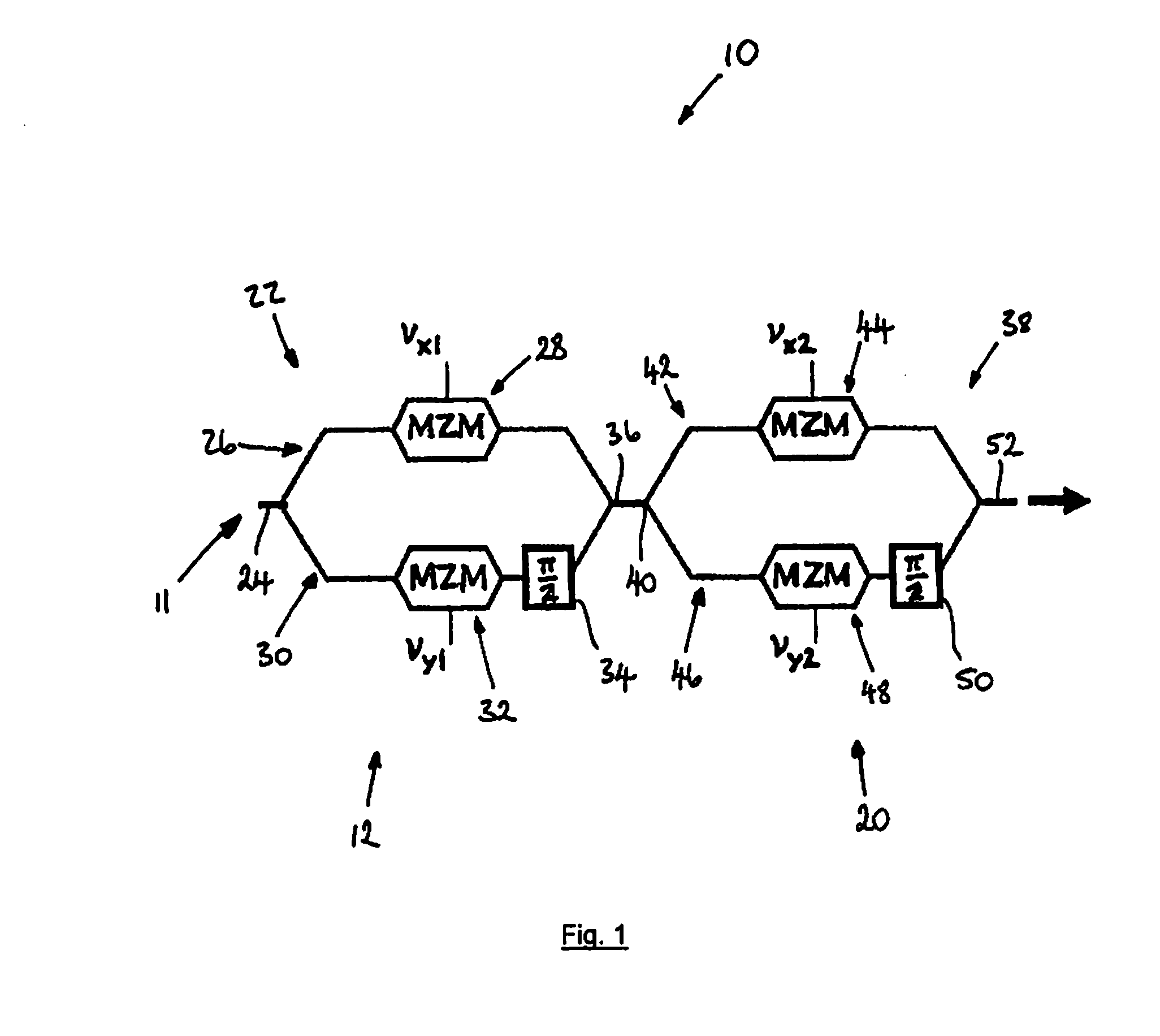
[0065]Referring to FIGS. 1 to 4, the invention provides a 2n-quadrature amplitude modulation (QAM) optical modulator in the form of a 16-QAM optical modulator 10 comprising an optical input 11, a first optical modulation apparatus 12, and a second optical modulation apparatus 20. In this embodiment, an optical signal to be modulated is received by the optical input 11 and coupled to the first optical modulation apparatus 12, which applies a quaternary aptitude modulation scheme to the optical signal, generating an intermediate optical signal.

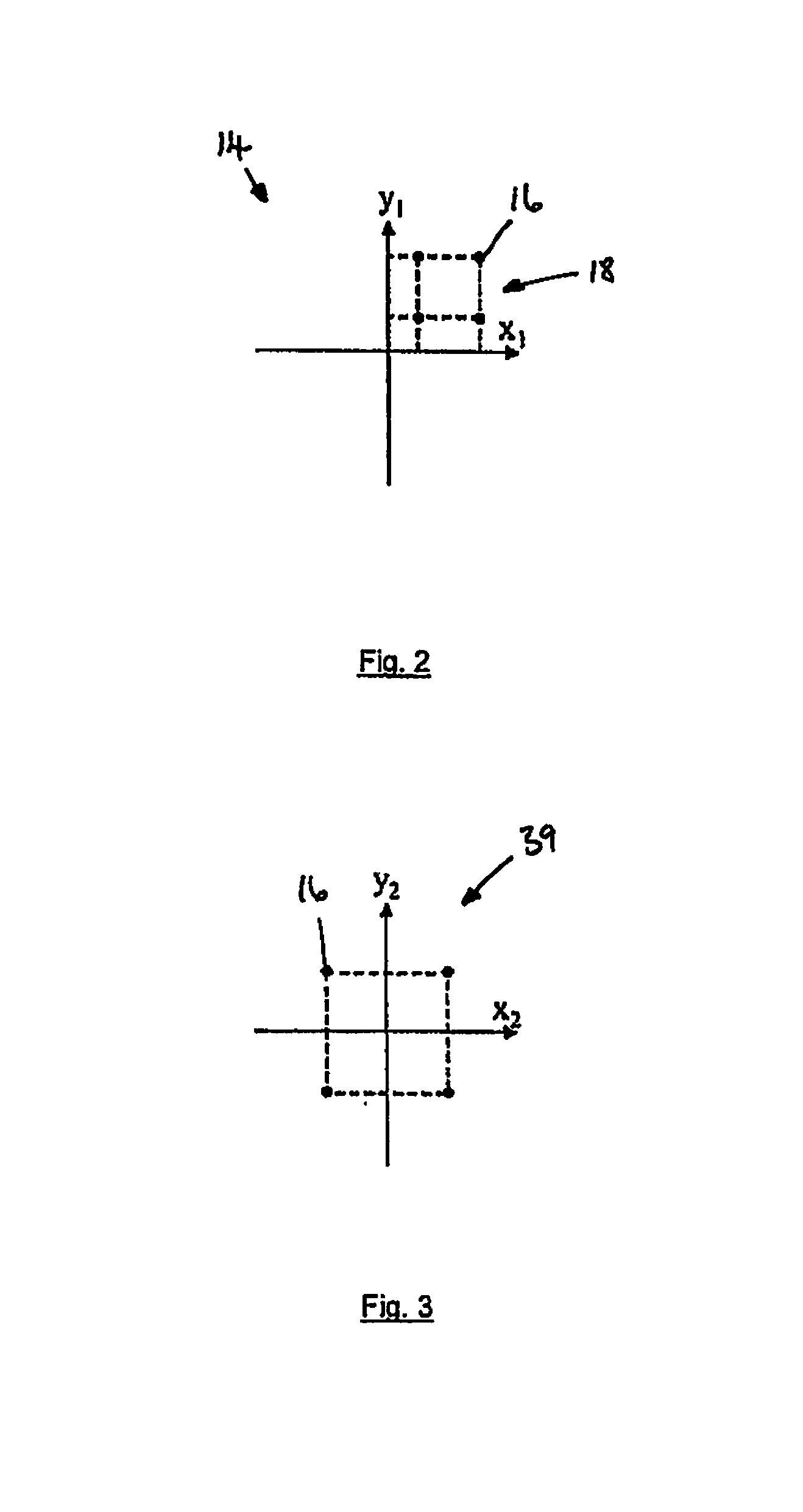
[0066]The intermediate optical signal is then delivered to the second optical modulation apparatus 20, which is configured to selectively rotate the phase of the intermediate optical signal. A 16-QAM modulated optical signal is thereby output from the optical modulator 10 which has a square constellation diagram 19, as shown in FIG. 4, comprising 16 constellation points 16 distributed across the 4 quadrants of the constellation diagram.

[0067]The...

second embodiment

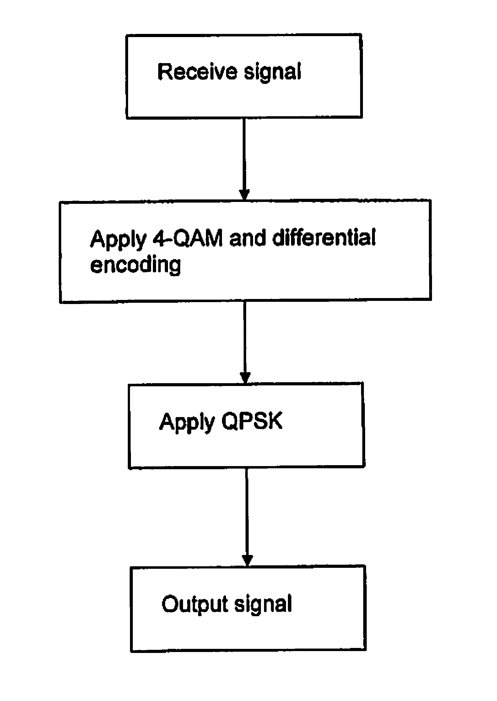
[0076]In use, a method of 16-QAM modulation according to the invention is implemented using the 16-QAM optical modulator 10, as illustrated in the flow diagram of FIG. 6a. An optical signal to be modulated is received by the optical input 11 of the 16-QAM optical modulator 10, and is coupled to the optical input 24 of the first I-Q modulator 22, which applies a quaternary amplitude modulation scheme (4-QAM) having the constellation diagram 14 shown in FIG. 2. Differential encoding is applied to the first two bits via the drive voltages (Vx1, Vy1) applied to the first and second Mach-Zehnder modulators 28, 32. The resulting intermediate optical signal output from the first I-Q modulator 22 is coupled to the input 40 of the second I-Q modulator 38, which applies a QPSK modulation having the constellation diagram 39 as shown in FIG. 3. The phase of the intermediate optical signal is thereby selectively rotated, causing the constellation points of the intermediate optical signal, as sho...

third embodiment

[0078]Referring to FIG. 7, the invention provides a 16-QAM optical modulator 60, which is substantially the same as the 16-QAM optical modulator 10 of FIG. 1, with the following modifications. The same reference numbers are retained for corresponding features.

[0079]In this embodiment, the second optical modulation apparatus 20 comprises a phase modulator 62 operable to selectively apply a phase rotation of 0°, 90°, 180° or 270° to the intermediate optical signal output from the first I-Q optical modulator 22. The phase rotation provided by the phase modulator 62 similarly inherently applies four quadrant differential encoding to the modulated optical signal.


PUM


Abstract

A 2n-QAM (e.g. 16-QAM) optical modulator comprising cascaded I-Q modulators. The first I-Q modulator applies 2n-2 (e.g. 4) QAM to an optical signal, having a constellation diagram with the 2n-2 (e.g., 4) constellation points located in quadrant I. The second I-Q modulator subsequently applies a quaternary phase-shift keying (QPSK) modulation scheme to the optical signal, thereby rotating the constellation points of the 2n-2-QAM modulation scheme to quadrants II, III and IV, to produce a 2n-QAM modulation constellation diagram. The rotation causes the 2n-QAM modulator to inherently apply four quadrant differential encoding to the optical signal. A method of 2n-QAM optical modulation is also provided and optical signal transmission apparatus comprising the 2n-QAM optical modulator.

Description

CROSS-REFERENCE TO RELATED APPLICATIONS[0001]This application claims the benefit of U.S. application Ser. No. 13 / 055,126, filed Jan. 20, 2011, which is a National Stage of PCT Application No. PCT / EP2008 / 061881, filed Sep. 8, 2008, which applications are hereby incorporated herein by reference in their entireties. This application claims priority under 35 U.S.C. §119 to European Patent Application No. 08161561.9, filed Jul. 31, 2008, which is hereby incorporated herein by reference in its entirety.TECHNICAL FIELD[0002]The invention relates to a 2n-quadrature amplitude modulation (QAM) optical modulator, a method of 2n-quadrature amplitude modulation, and optical signal transmission apparatus comprising the 2n-QAM optical modulator.BACKGROUND[0003]Quadrature amplitude modulation with 16 levels (16-QAM) is one of the candidate modulation formats for 100 Gigabit / s (Gbit / s) transmission into optical fibre. It encodes four bits on a constellation of sixteen points, with four different amp...

Claims


Application Information

Patent Timeline
IPC IPC(8): H04B10/54H04B10/516H04B10/548
CPCH04B10/541G02F1/225G02F2201/16H04B10/5161H04B10/548H04L27/2096H04L27/3488H04L27/36
Inventor SECONDINI, MARCOCAVALIERE, FABIO
Owner TELEFON AB LM ERICSSON (PUBL)
Why Eureka
Try Eureka