
Transmitting device, receiving device, transmitting method, program, and integrated circuit

Inactive Publication Date: 2015-05-07
SHARP KK
View PDF5 Cites 18 Cited by
  • Summary
  • Abstract
  • Description
  • Claims
  • Application Information

AI Technical Summary

Benefits of technology

The present invention improves the transmission of signals to multiple mobile devices by using hierarchical modulation in the downlink. This improves cell throughput and spectral efficiency.

Problems solved by technology

In a mobile communication system, the system band has been widened due to an upsurge in traffic, and an improvement in spectral efficiency is an issue because frequencies are a limited resource.
While these adopted access schemes are approaches to achieve large-capacity transmission based on FDMA, keeping orthogonality is restrictive in view of an improvement in spectral efficiency.

Method used


Image

  • Transmitting device, receiving device, transmitting method, program, and integrated circuit
  • Transmitting device, receiving device, transmitting method, program, and integrated circuit
  • Transmitting device, receiving device, transmitting method, program, and integrated circuit

Examples


first embodiment

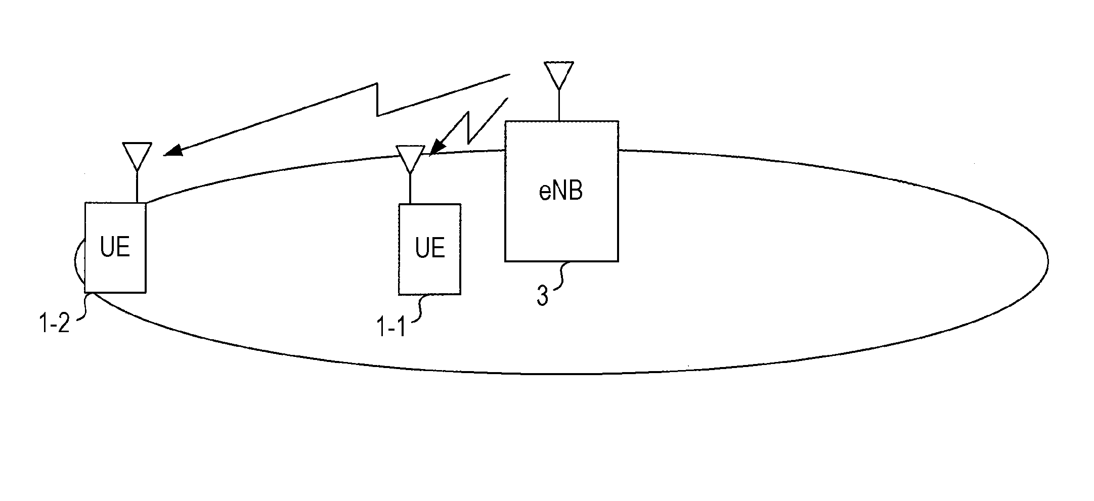
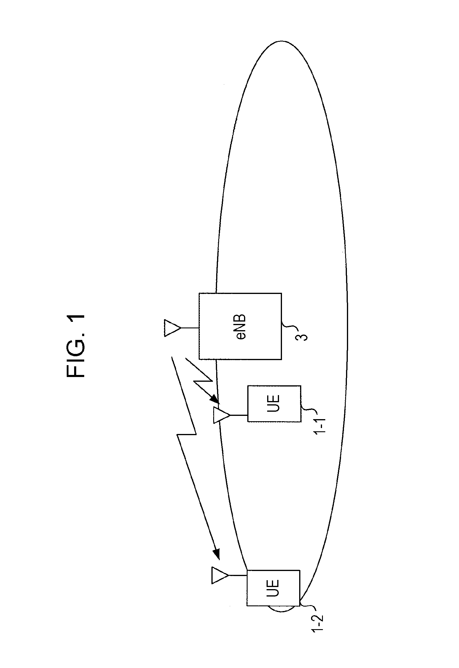
[0051]FIG. 1 is a schematic diagram depicting a communication system according to a first embodiment of the present invention. In this drawing, the communication system includes mobile station devices UE1-1 and UE1-2 (the mobile station devices UE1-1 and UE1-2 are hereinafter also collectively represented as a mobile station device UE1 or mobile station device 1) and a base station device eNB3 (hereinafter also represented as a base station device 3). When performing data transmission to at least two or more mobile station devices 1, the base station device 3 selects a transmission scheme for use in data transmission from either one of an orthogonal access scheme and a non-orthogonal access scheme. When data transmission by the non-orthogonal access scheme is performed, the mobile station device 1 to which the non-orthogonal access scheme is applied is selected. Furthermore, after notifying the selected mobile station device 1 of information required for the mobile station device 1 ...

second embodiment

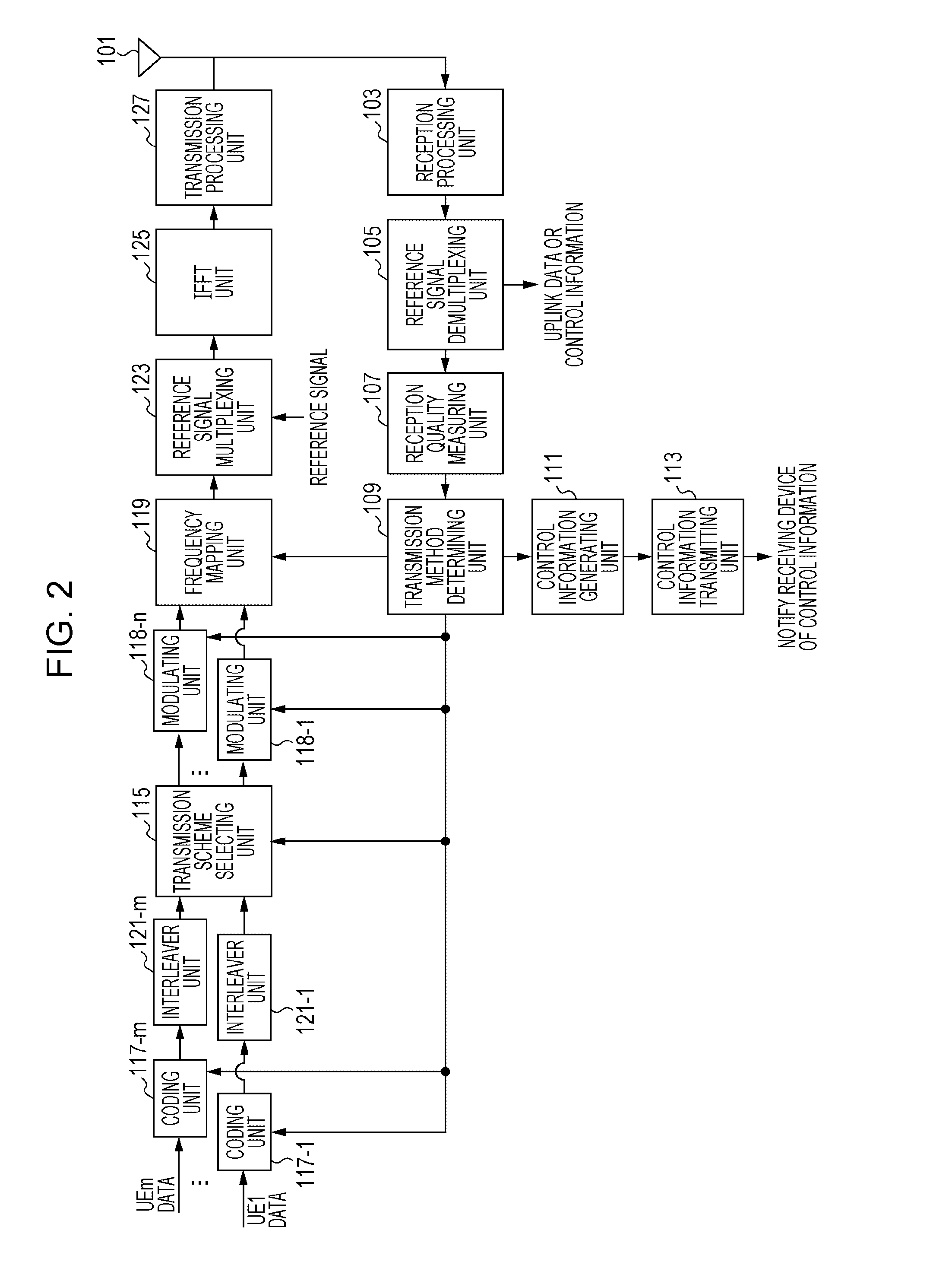
[0085]While the ratio of signals to be assigned to each layer is fixed in the previous embodiment, the ratio is controlled in the present embodiment. The structures of a transmitting device and a receiving device in the present embodiment are similar to those of the above-described first embodiment, and are as in FIG. 2 and FIG. 9, respectively. However, the processes of the transmission method determining unit 109 and the modulating units 118-1 to 118-n of the transmitting device are different. Since other processes are similar, they are not described herein.

[0086]The transmission method determining unit 109 determines a transmission scheme, MCS, frequency assignment, and so forth for use in data transmission to each mobile station device 1 based on the inputted channel performance of the mobile station devices UE1-1 to UE1-m. The transmission scheme determines, in addition to information indicating which of the orthogonal access scheme or the non-orthogonal access scheme is to be ...

modification example of second embodiment

[0093]A modification example in the second embodiment is described. While it is predicated in the second embodiment that a notification of the information about the ratios of assignment to the first layer and the second layer is made as control information, the case is described in the present modification example in which a notification is not made as control information. The structures of a transmitting device and a receiving device in the present modification example are similar to those of the first and second embodiments, and are as in FIG. 2 and FIG. 9, respectively. However, only the transmission method determining unit 109 of the transmitting device is different from that of the second embodiment.

[0094]The transmission method determining unit 109 determines a transmission scheme, MCS, frequency assignment, and so forth for use in data transmission to each mobile station device 1 based on the inputted channel performance of the mobile station devices UE1-1 to UE1-m. The trans...


PUM


Abstract

When signals to be transmitted to a plurality of mobile station devices are multiplexed by hierarchical modulation in a downlink, an increase in difference in reception quality among the mobile station devices is prevented. A transmitting device of the present invention is a transmitting device which performs data transmission to a plurality of receiving devices by using a plurality of symbols and a plurality of layers with different distances between signal points, and includes a modulating unit 118-n which assigns data to be transmitted to a first receiving device to a first layer in a predetermined symbol of the plurality of symbols and assigns data to be transmitted to a second receiving device different from the first receiving device to the first layer in remaining symbols and a transmission processing unit 127 which transmits each data assigned to the first layer to the first receiving device and the second receiving device.

Description

TECHNICAL FIELD[0001]The present invention relates to technology of transmitting data from a base station device to a plurality of mobile station devices.BACKGROUND ART[0002]In a mobile communication system, the system band has been widened due to an upsurge in traffic, and an improvement in spectral efficiency is an issue because frequencies are a limited resource. In communication between a base station device and a plurality of mobile station device, an access scheme is generally used in which orthogonality among the mobile station devices is kept to prevent interference (also referred to as inter user interference) among the mobile station devices, and standardization has been made in recent years on the premise of frequency division multiple access (FDMA), which is an access scheme for keeping orthogonality. In FDMA, frequency scheduling and orthogonality can be both achieved. Note that other than orthogonalization by FDMA, means for achieving orthogonalization among the mobile...

Claims


Application Information

Patent Timeline
IPC IPC(8): H04L27/26
CPCH04L27/2627H04L27/2604H04L27/3488
Inventor GOTO, JUNGOTAKAHASHI, HIROKINAKAMURA, OSAMUYOKOMAKURA, KAZUNARIHAMAGUCHI, YASUHIRO
Owner SHARP KK
Learn More