
Device for monitoring an operation of an inductive element

a technology of inductive elements and devices, applied in measurement devices, electrical testing, instruments, etc., can solve the problems of difficult or impossible detection, real effect of inductive element operation, etc., and achieve the effect of saving work and costs, reducing scanning rate, and saving work and costs

Active Publication Date: 2015-05-07
ROBERT BOSCH GMBH
View PDF9 Cites 1 Cited by
  • Summary
  • Abstract
  • Description
  • Claims
  • Application Information

AI Technical Summary

Benefits of technology

The device according to the present invention operates with digital signals, which makes it possible to have a simplified and cost-effective structure. The use of digital signals also improves the temperature stability of the device. Additionally, the device can alternatively monitor inductive elements having different sizes, which makes it more flexible and easier to use. Instead of predefining measuring moments, the device is able to capture data throughout the measurement process, making it more robust against changes in the inductive element. Furthermore, the device does not require time synchronization and can handle switching flanks of different steepness. Its low-resistance configuration also makes it more advantageous. The method described in the patent text simplifies processing by using signals with reduced resolution.

Problems solved by technology

If the shunt features relatively high resistance, then it may be difficult or impossible to detect it, but it has no real effect on the operation of the inductive element.

Method used


Image

  • Device for monitoring an operation of an inductive element
  • Device for monitoring an operation of an inductive element
  • Device for monitoring an operation of an inductive element

Examples


Embodiment Construction

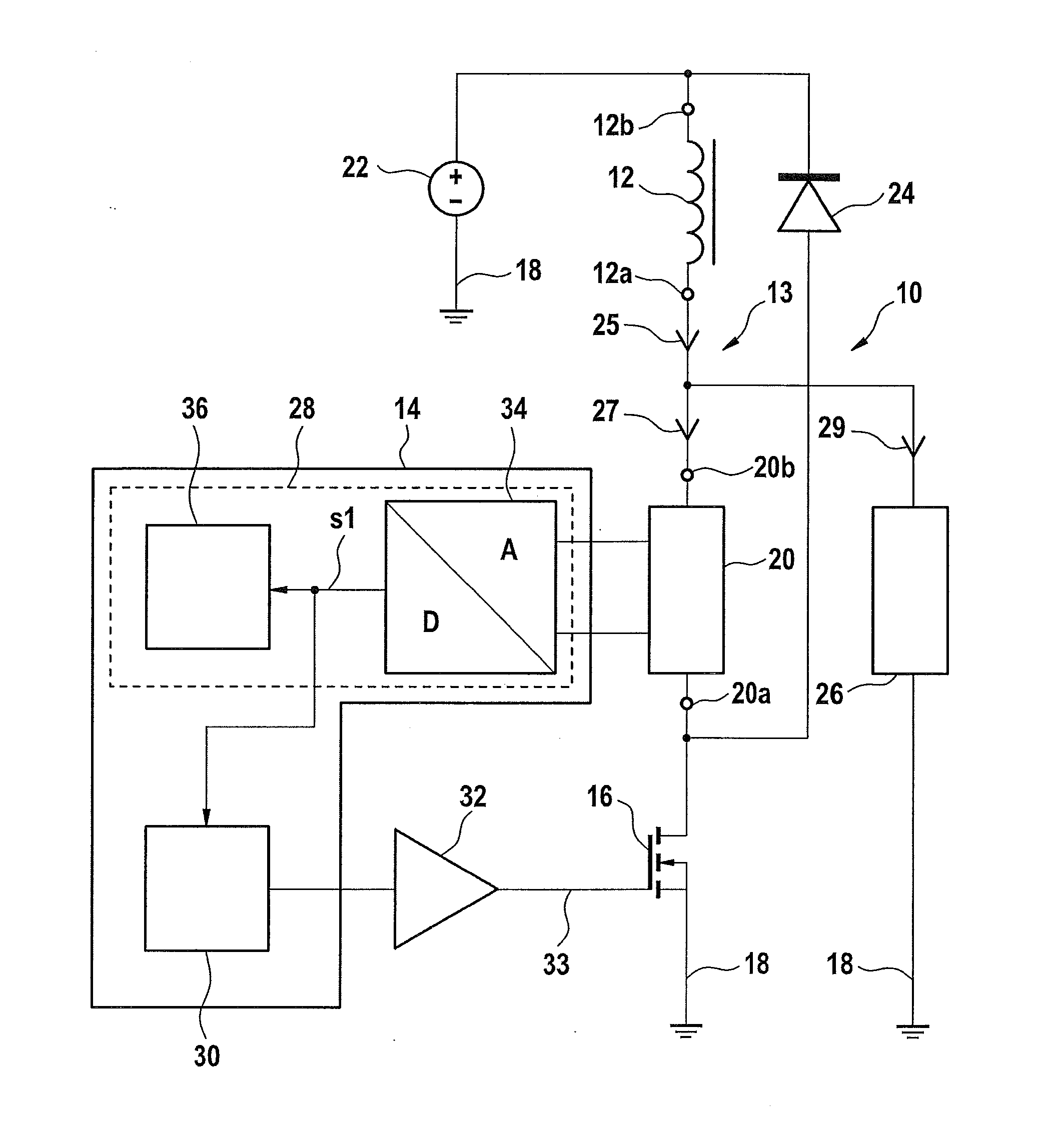
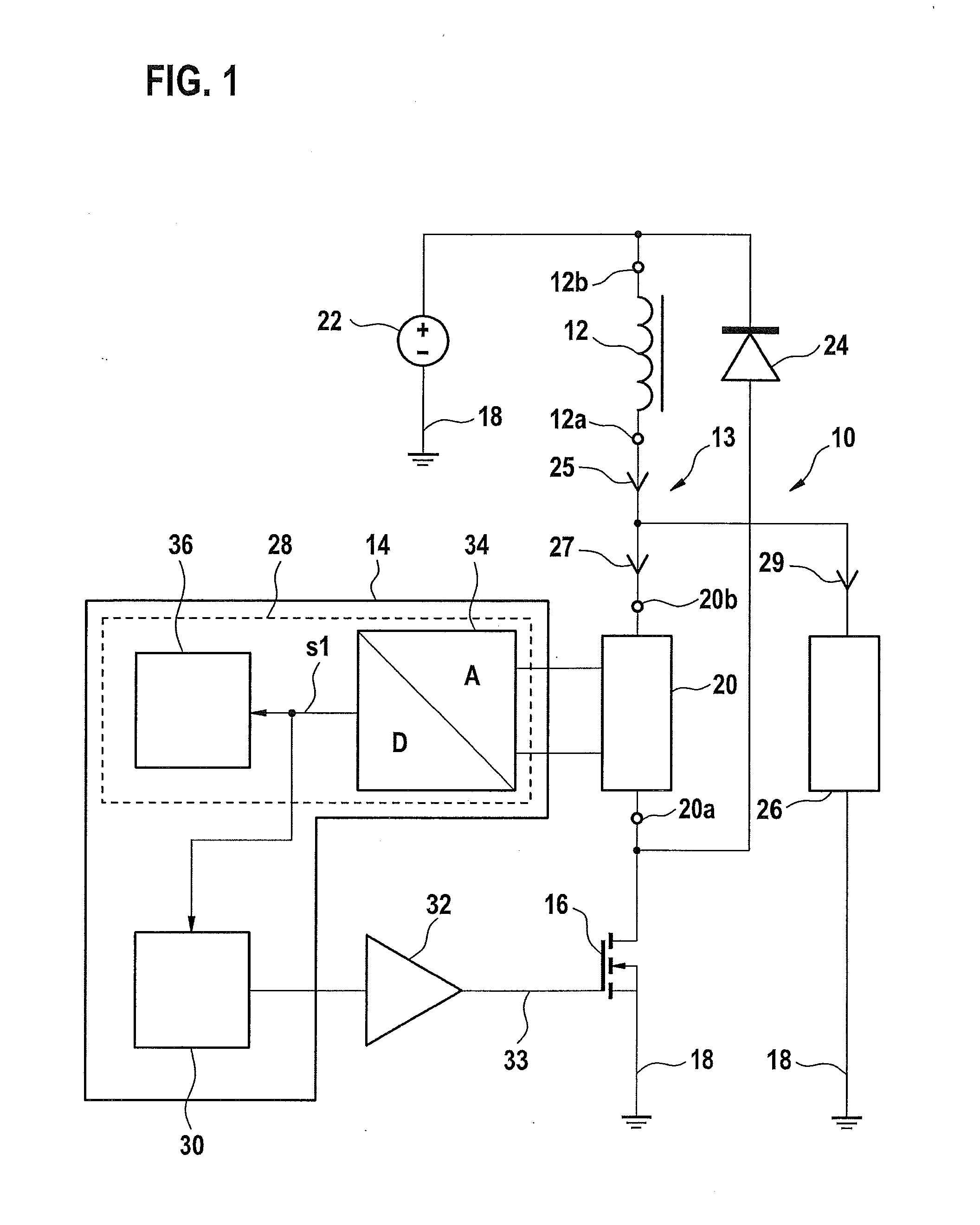
[0043]FIG. 1 shows an electronic circuit 10 for actuating an inductive element 12 in a right region of the figure, and in a left region a control and / or regulation device 14 for operating electronic circuit 10 and, in particular, for monitoring the operation of inductive element 12. In this case inductive element 12 is a solenoid coil of an electromagnetic actuating device for a transmission control system for an automatic transmission of a motor vehicle.

[0044]Electronic circuit 10 includes a semiconductor switch 16, which is implemented as a MOSFET in this instance (metal oxide silicon field effect transistor) and is connected via an S-terminal (source) to a reference potential, i.e., to a zero potential 18. A D-terminal (drain) of semiconductor switch 16 is connected to a first terminal 20a of a current-measuring device 20, which is realized as (Ohmic) measuring resistor in this instance. A second terminal 20b of current-measuring device 20 is connected to a first terminal 12a of ...


PUM


Abstract

A device for monitoring an operation of an inductive element, includes a current-measuring device is switched in series with the inductive element. The device is configured to ascertain a first time-discrete and value-discrete signal, which characterizes a current flowing through the current-measuring device; to ascertain a second time-discrete and value-discrete signal, which characterizes a current flowing through the current-measuring device and has a predefinable time shift in relation to the first signal; and to infer the presence of a shunt from a comparison of the first signal with the second signal. Also described is a method for monitoring the operation of the inductive element.

Description

RELATED APPLICATION INFORMATION[0001]The present application claims priority to and the benefit of German patent application no. 10 2013 222 405.2, which was filed in Germany on Nov. 5, 2013, the disclosure of which is incorporated herein by reference.FIELD OF THE INVENTION[0002]The present invention relates to a device, and to a related method.BACKGROUND INFORMATION[0003]Electromagnetic actuating devices, for instance for a transmission control system of an automatic transmission of a motor vehicle or for a fuel injector of an internal combustion engine, are known from the market. An inductive element in these devices is energized for a predefinable period of time using a defined average value of a current. In particular, the inductive element is periodically switchable, at a predefinable frequency and a predefinable pulse control factor, to an operating voltage, from which said average value results and subsequently, a certain opening cross-section of a valve, for example.[0004]An...

Claims


Application Information

Patent Timeline
Patent Type & Authority Applications(United States)
IPC IPC(8): G01R31/06G01R31/72
CPCG01R31/06G01R31/72
Inventor MARTINIMUELLER, BERNDGUENTHER, UWEMELI, BERTRAND ERICHENKEL, FRANK
Owner ROBERT BOSCH GMBH
Learn More