Method and apparatus for determination of a magnetic resonance system control sequence

a magnetic resonance system and control sequence technology, applied in the direction of reradiation, measurement using nmr, instruments, etc., can solve the problems of discretization errors, delay, jitter, inadequacies of gradient system hardware, etc., and achieve the effect of significantly simplifying and speeding up the calculation method

Active Publication Date: 2015-04-23
SIEMENS HEALTHCARE GMBH
View PDF3 Cites 9 Cited by
  • Summary
  • Abstract
  • Description
  • Claims
  • Application Information

AI Technical Summary

Benefits of technology

[0016]Within the RF pulse optimization method, a high bandwidth of hypothetical gradient errors that could occur within the subsequent measurement can thus be covered, such that the optimized radio-frequency pulse shape or the radio-frequency pulse train that is obtained is less sensitive with regard to such gradient errors. As will be explained in more detail below, data of a current measurement of the trajectory curve that is actually achieved can be foregone via this combination of different models. The method according to the invention is thus rapid, as well as robust, in the calculation. This consequently leads to a speed improvement, and to a better image quality in the overall measurement.
[0022]Significant portions of the control sequence determination device can be designed in the form of software components. This is particularly the case for the trajectory determination unit and the RF pulse optimization unit or their components, for example a target function determination unit. The aforementioned interfaces can likewise be designed at least in part in the form of software and may possibly be hardware interfaces of an existing computer. The invention thus also encompasses a non-transitory, computer-readable data storage medium encoded with program code that can be loaded directly into a memory of a control sequence determination device, with program code segments in order to execute all steps of the method according to the invention when the program code is executed in the control sequence determination device. Such a realization has the advantage that previous devices that are used to determine control sequences (for example suitable computers in computing centers of the magnetic resonance system manufacturers) can also be suitably modified b implementation of the program code in order to determine fast and robustly optimized control sequences in the manner according to the invention.
[0035]Independent of whether the different trajectory error models are based on the same trajectory error model type and have only different error parameters, or whether the trajectory error models are also based on different trajectory error model types, these can enter into the target function with a predetermined weighting, which means that (for example) a specific error type can be more strongly weighted than other error types. For this purpose, simple weighting factors for each trajectory error model or each trajectory error model type can predetermined within the target function.
[0042]The calculation of the radio-frequency pulse train within the scope of the RF pulse optimization method particularly preferably initially takes place for a lower target magnetization. The multichannel pulse train that is thereby determined is subsequently scaled up to an ultimate target magnetization and is post-corrected again as necessary. For this procedure it is utilized that the magnetization response is still linear for small magnetizations, i.e. for small flip angles (in what is known as the “low flip range”), for example between 0° and 5°. Therefore, in this range a calculation with an optimization method is significantly simpler and faster. If the optimal multichannel pulse train is found for this range, an upscaling is possible without further measures in a subsequent step. For example, if the calculation in the low flip range takes place for a flip angle of at most α=5°, and the actual magnetization should take place with a flip angle α of at most 90°, the amplitude values of the RF pulses can by multiple by a factor of 18 (corresponding to the ratio of the flip angles).

Problems solved by technology

However, in practice a problem is that these calculations always assume that the trajectory is ideally implemented precisely as it is mathematically defined in the optimization method.
Typical reasons for this are the inadequacies of the gradient system hardware, for example delays, jitter, discretization errors or additional gradient terms that can occur because of induced eddy currents or other effects such as mixing Maxwell terms of different gradient coils.
However, all of these methods require a prior measurement of the actual emitted trajectories, which is very time-consuming.

Method used


Image

  • Method and apparatus for determination of a magnetic resonance system control sequence
  • Method and apparatus for determination of a magnetic resonance system control sequence
  • Method and apparatus for determination of a magnetic resonance system control sequence

Examples


Embodiment Construction

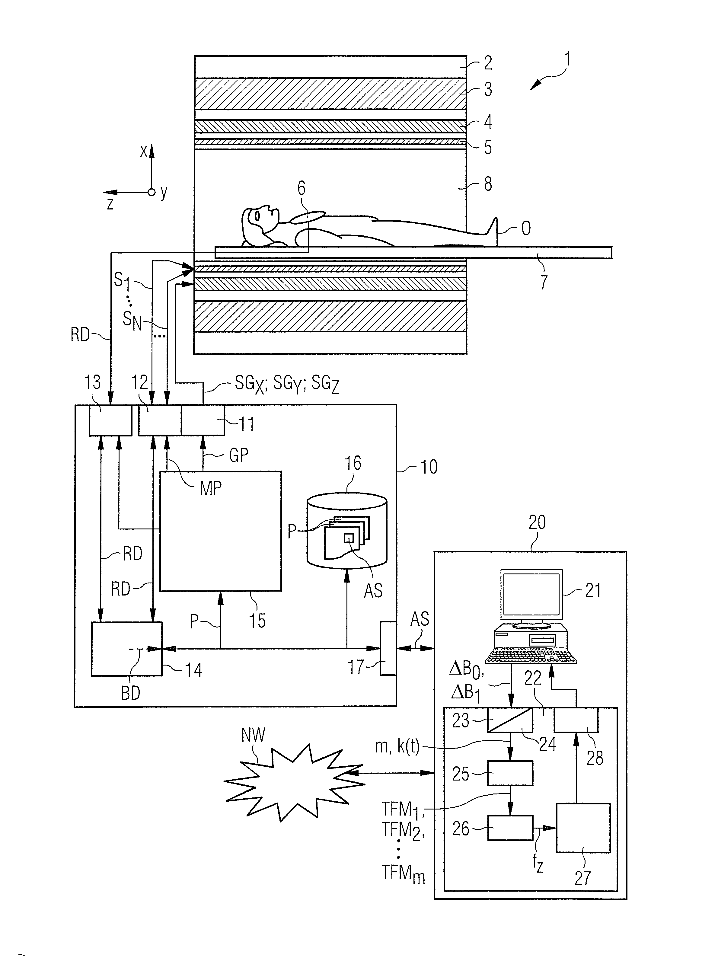
[0047]A magnetic resonance system 1 according to the invention is schematically depicted in FIG. 1. The system includes the actual magnetic resonance scanner 2 with an examination space 8 or patient tunnel therein. A bed 7 can be driven into this patient tunnel 8 so that, during an examination, an examination subject 0 (patient / test subject) lying on said bed 7 can be supported at a defined position within the magnetic resonance scanner 2 relative to the magnet system and radio-frequency system arranged therein, or can be driven between different positions during a measurement.

[0048]Basic components of the magnetic resonance scanner 2 are a basic field magnet 3, a gradient system 4 with magnetic field gradient coils in order to apply arbitrary magnetic field gradients in the x-, y- and z-directions, and a whole-body radio-frequency coil 5. The reception of magnetic resonance signals induced in the examination subject O can take place via the whole-body coil 5 with which the radio-fr...


PUM


Abstract

In a method and a control sequence determination device for determining a magnetic resonance system control sequence includes at least one radio-frequency pulse train to be emitted by a magnetic resonance system, a target magnetization is acquired and a k-space trajectory is determined. A radio-frequency pulse train for the k-space trajectory is then determined in an RF pulse optimization method using a target function, wherein the target function includes a combination of different trajectory curve functions, of which at least one trajectory curve function is based on a trajectory error model. A method for operating a magnetic resonance system uses such a control sequence and a magnetic resonance system has such a control sequence determination device.

Description

BACKGROUND OF THE INVENTION[0001]1. Field of the Invention[0002]The invention concerns a method and a control sequence determination device to determine a magnetic resonance system control sequence. Moreover, the invention concerns a method to operate a magnetic resonance system using such a magnetic resonance system control sequence, as well as a magnetic resonance system with a radio-frequency transmission device, with a gradient system, and a control device designed in order to emit a radio-frequency pulse train to implement a desired measurement on the basis of a predetermined control sequence, and in coordination with this to emit a gradient pulse train.[0003]2. Description of the Prior Art[0004]In a magnetic resonance (MR) tomography system (shortened to “magnetic resonance system”), the body to be examined is typically exposed to a relatively high basic field magnet field (what is known as the B0 field)—for example 3 or 7 Tesla—with the use of a basic field magnet system. In ...

Claims


Application Information

Patent Timeline
Patent Type & Authority Applications(United States)
IPC IPC(8): G01R33/54G01R33/34G01R33/30G01R33/385G01R33/48
CPCG01R33/546G01R33/3852G01R33/34076G01R33/307G01R33/4818G01R33/4833G01R33/56572
Inventor PFEUFFER, JOSEFSCHNEIDER, RAINER
Owner SIEMENS HEALTHCARE GMBH
Why Eureka
Try Eureka