
Coaxial direct drive system

a direct drive and coaxial technology, applied in the field of coaxial direct drive systems, can solve the problems of large and expensive manufacturing of required hollow drive shafts, large weight and/or mass of drive shafts, and complex systems that can be fragile and/or difficult to service and/or maintain

Active Publication Date: 2015-04-23
LIVINGSTON EDWARD
View PDF16 Cites 1 Cited by
  • Summary
  • Abstract
  • Description
  • Claims
  • Application Information

AI Technical Summary

Benefits of technology

This patent text describes a new coaxial direct drive system that solves problems in previous systems. The system includes two prime movers, each with a stator and rotor, that rotate around a common axis. Each rotor has a driven member that rotates with it and can be attached to objects to be driven. The motor carrier member can be attached to the object or to a support mast. The technical effect of this system is that it allows for more efficient and reliable propulsion of objects.

Problems solved by technology

While such systems have been employed for many years, they suffer from disadvantages in that the required hollow drive shaft tends to be large and expensive to fabricate, the weight and / or mass of the drive shafts tends to be large and the configuration and arrangement of the overall coaxial system tends to be constrained by the requirements for the nested drive shafts.
In flight-related coaxial designs, such as those employed for helicopters, the weight of the nested drive shafts and the mechanical complexities of mounting such systems and operably connecting them to respective prime mover systems has resulted in expensive and / or complex systems which can be fragile and / or difficult to service and / or maintain.
However, such systems still suffer from the disadvantages of requiring coaxially arranged drive shafts to which the helicopter rotors can be attached.
Such systems also require appropriate transmissions and / or complex linkages to transfer the torque produced by the electric motors to the drive shafts and then to the rotors and such transmissions and linkages increase cost, weight and complexity, which can reduce the reliability of such systems.

Method used


Image

  • Coaxial direct drive system
  • Coaxial direct drive system
  • Coaxial direct drive system

Examples


Embodiment Construction

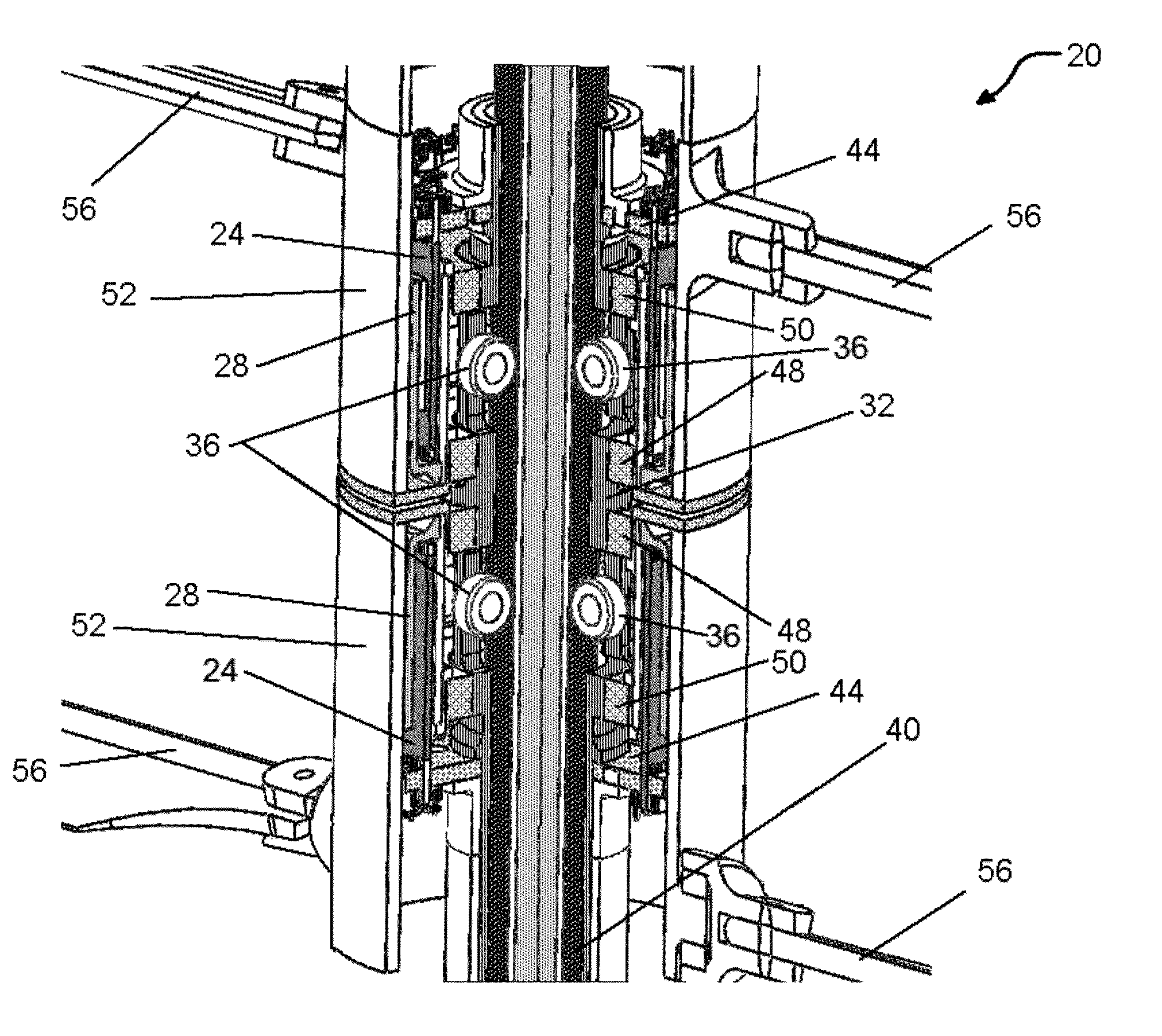
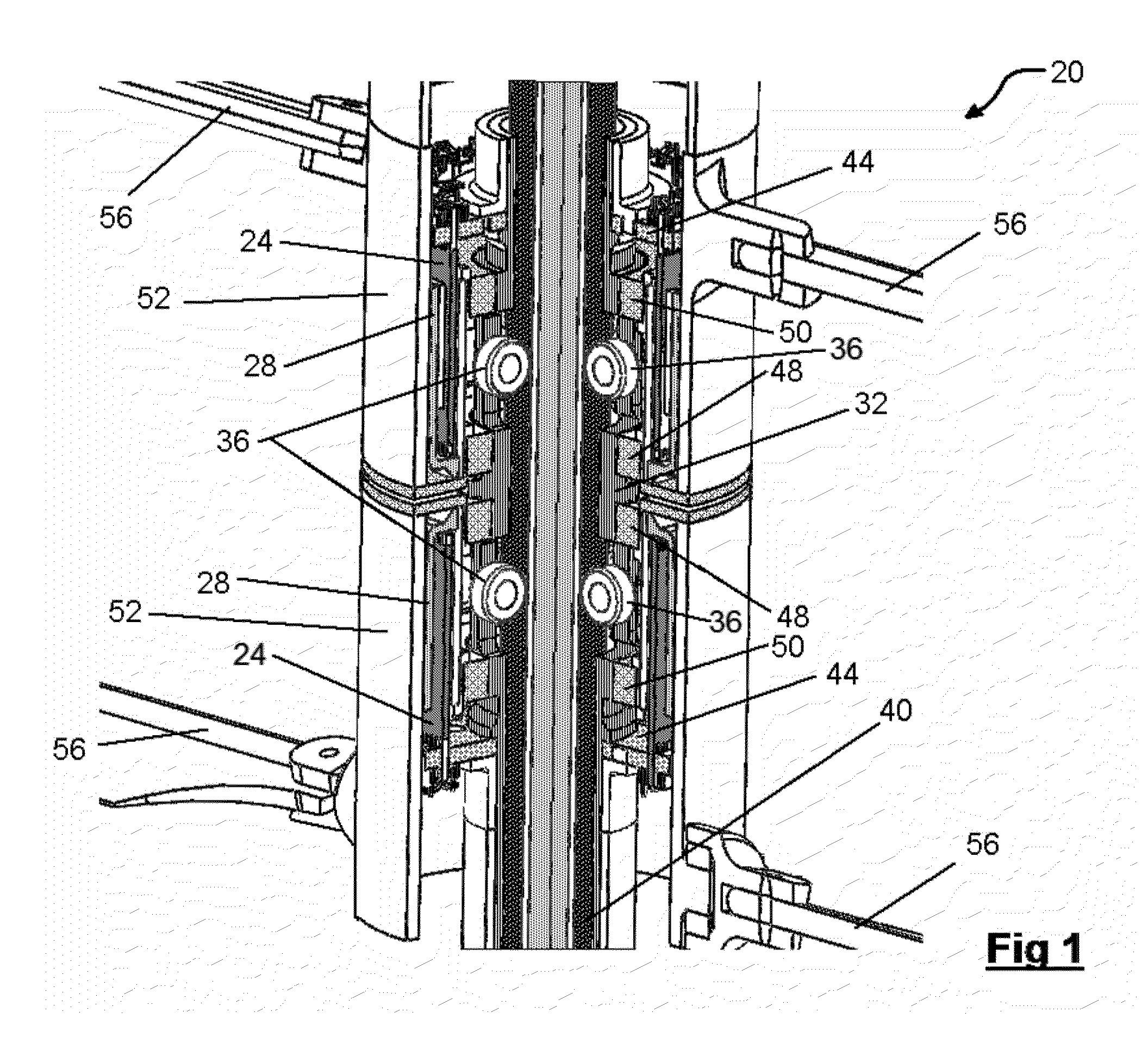
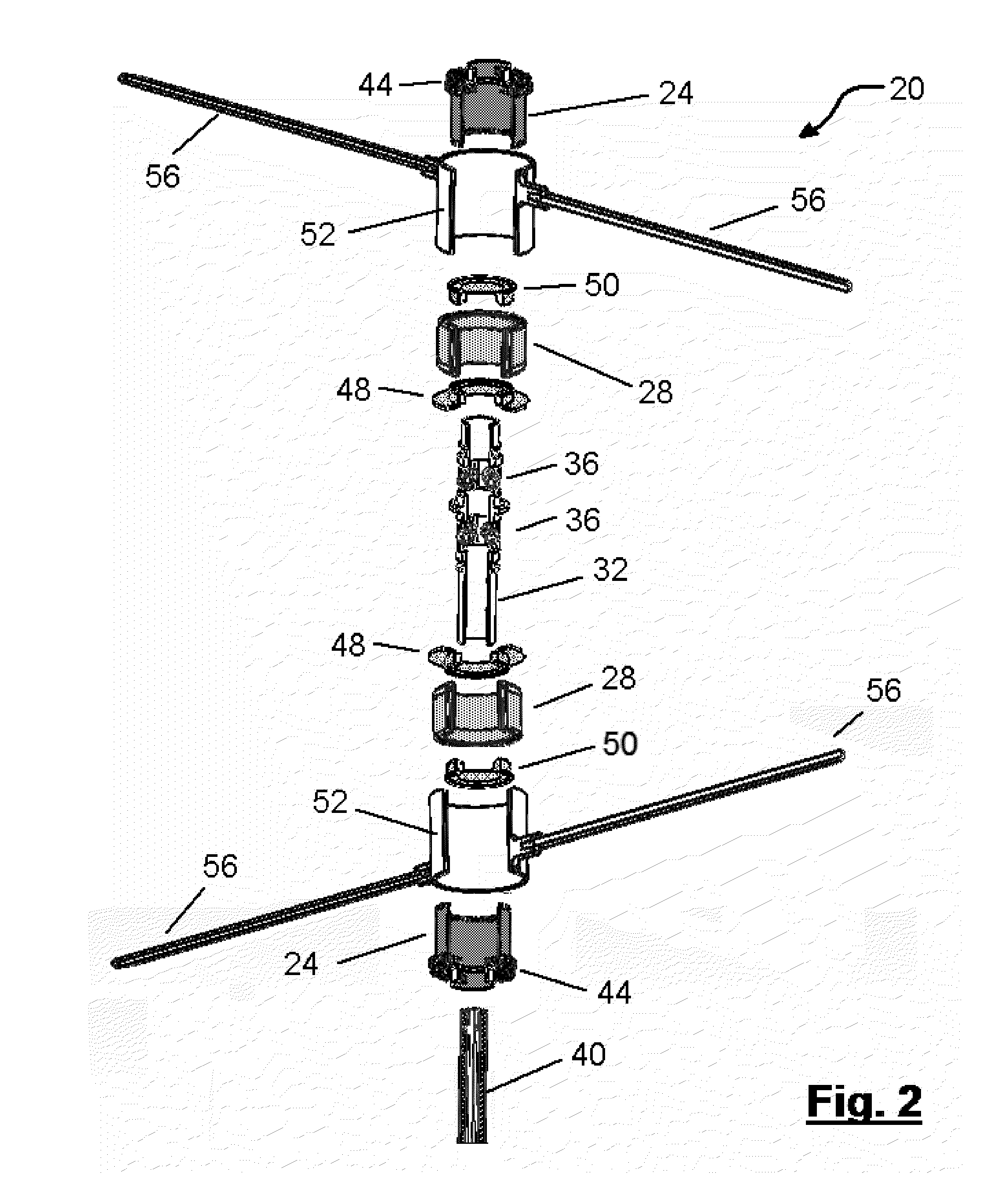
[0015]A coaxial direct drive system in accordance with the present invention is indicated generally at 20 in FIGS. 1 and 2. Drive system 20 includes at least two prime movers, and in the illustrated example, these prime movers are electric motors, each comprising an annular stator 24 and an annular rotor 28.

[0016]In a presently preferred embodiment, the particular electric motors are brushless DC ring motors, such as the model TG2320 Brushless Motor, commercially available from ThinGap, 2064 Eastman Avenue, Ventura Calif., USA. However, as will be apparent to those of skill in the art, the present invention is not limited to use with these particular electric motors and any other suitable electric annular-design motors can be employed, including commutated (brushed) DC motors, or variable speed AC motors, etc.

[0017]While not shown in FIGS. 1 and 2, stators 24 are electrically connected to a suitable power supply, and stators 24 are mounted to a motor carrier member 32. In the illust...


PUM


Abstract

A coaxial direct drive system includes at least two prime movers mounted to a motor carrier member about a common axis. Each prime mover includes a stator affixed to the motor carrier member, and each prime mover further includes a rotor which can rotate about the common axis. Each rotor has a driven member affixed to it, which rotates with the respective rotor, and to which driven objects, such as aero foil blades, etc. can be affixed. The motor carrier member can be directly mounted to an object to be propelled by the coaxial direct drive system, or can be hollow to receive a support mast which is mounted to the object to be driven. The driven objects can have different rotational senses, such that when the prime movers counter rotate, the driven objects generate trust in the same direction.

Description

FIELD OF THE INVENTION[0001]The present invention relates to a coaxial direct drive system. More specifically, the present invention relates to a coaxial direct drive system having at least two prime movers arranged coaxially along an axis.BACKGROUND OF THE INVENTION[0002]Coaxial drive systems are well known and are commonly employed where it is desired to reduce undesired gyroscopic or rotational moment forces acting on the driven vehicle or device. For example, underwater vessels such as torpedoes and submarines often employ counter-rotating coaxially arranged propellers so that the tendency for the vessel to rotate with respect to a fixed propeller, rather than the propeller rotating with respect to the fixed vessel, is reduced. Similarly, some airplanes employ counter-rotating propellor systems to reduce the effects of propellor torque.[0003]However, in all known coaxial drive systems, one drive is achieved via a first drive shaft which is hollow (which connects a prime mover to...

Claims


Application Information

Patent Timeline
IPC IPC(8): H02K16/00B63H5/10B63G8/08H02K7/14F42B19/24B64D27/24B64D35/06B63H1/02B63H21/17
CPCH02K16/00B63H1/02B63H5/10B63G8/08H02K7/14F42B19/24B64D27/24B64D35/06B63H21/17B63H1/14Y02T50/60
Inventor LIVINGSTON, EDWARD
Owner LIVINGSTON EDWARD
Learn More