Tool changer provided with covers
a tool changer and cover technology, applied in the direction of manufacturing tools, precision positioning equipment, metal-working machine components, etc., can solve the problems that the chip produced during machining and a cutting fluid may possibly get into the turret, and the structural parts of the turret b>6/b> may be adversely affected
- Summary
- Abstract
- Description
- Claims
- Application Information
AI Technical Summary
Benefits of technology
Problems solved by technology
Method used
Image

Examples
first embodiment
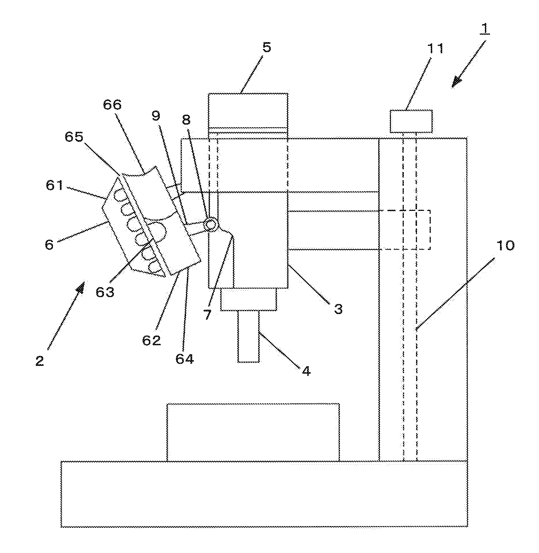
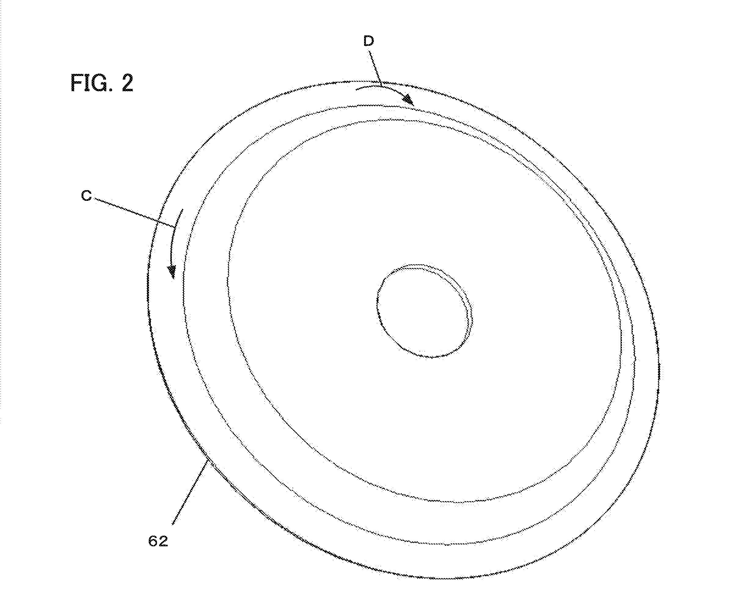
[0027]First, a tool changer according to the present invention will be described with reference to FIG. 1.
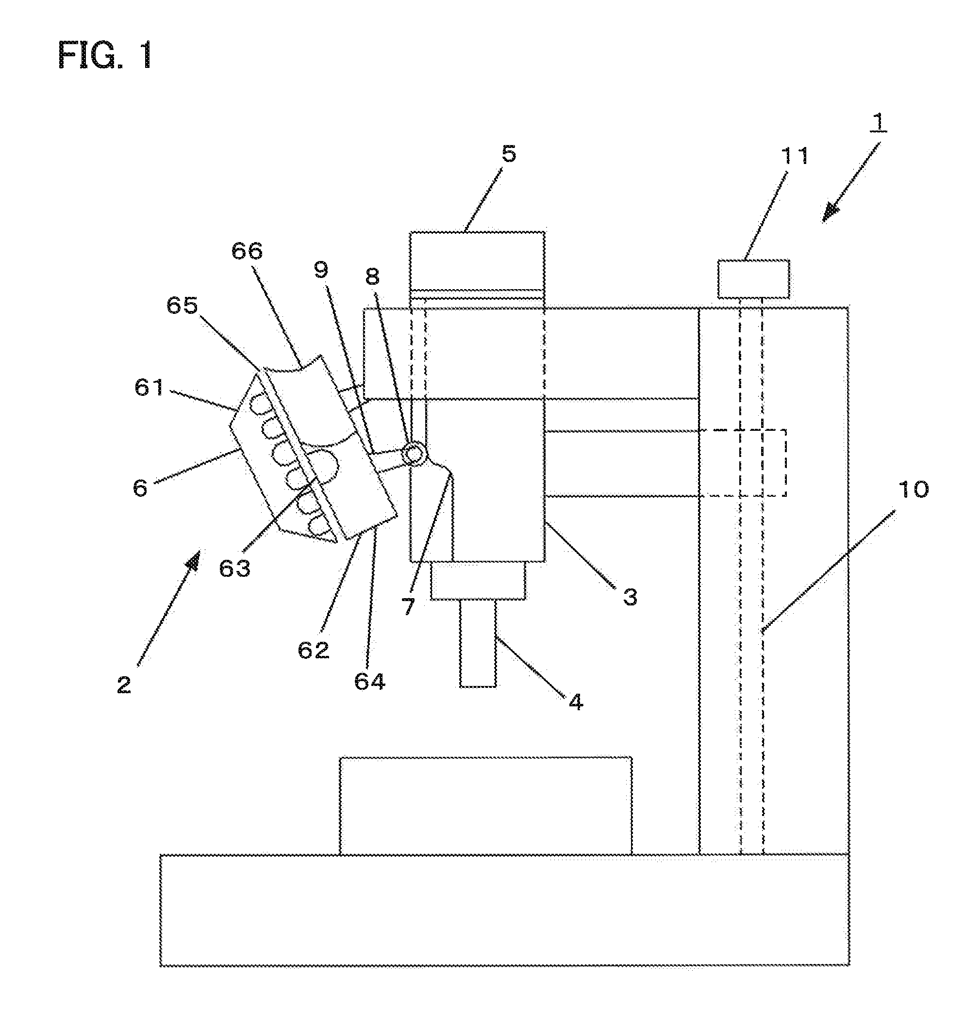
[0028]The tool changer of this embodiment differs from the prior art tool changer shown in FIG. 11 in that a recess 66 with a semicircular cross-section is provided in an upper part (corresponding to region A of FIG. 11) of an outer peripheral portion of a rear cover 62, as shown in FIG. 1. Thus, chips produced as a workpiece is machined and a cutting fluid used in machining the workpiece are guided left and right relative to a front cover 61, as indicated by arrows C and D in FIG. 2, so that they can be prevented from getting into a turret 6 through a gap 65 defined between the front and rear covers 61 and 62.
[0029]The turret 6 is provided with a plurality of grips for holding a tool 4.
[0030]In changing the tool 4, a spindle 3 is driven to move vertically by a Z-axis motor 11. Since the spindle 3 is provided with a cam 7, the turret 6 is swung by a cam follower 8 that follows t...
second embodiment
[0037]the tool changer according to the present invention will now be described with reference to FIG. 7.
[0038]The tool changer of this embodiment differs from the tool changer of the first embodiment in that a projection is provided in place of the recess on an upper part (corresponding to region A of FIG. 11) of an outer peripheral portion of a rear cover 62.
[0039]In this embodiment, a projection 70 with a triangular cross-section is provided on the upper part of the outer peripheral portion of the rear cover 62. Thus, chips produced as a workpiece is machined and a cutting fluid used in machining the workpiece are guided left and right relative to a front cover 61, as indicated by arrows C and D in FIG. 2, so that they can be prevented from getting into a turret 6 through a gap 65 defined between the front and rear covers 61 and 62.
[0040]In changing the tool 4, a spindle 3 is driven to move vertically by a Z-axis motor 11. Since the spindle 3 is provided with a cam 7, the turret ...
PUM
 Abstract
Description
Claims
Application Information
 - R&D
- Intellectual Property
- Life Sciences
- Materials
- Tech Scout
- Unparalleled Data Quality
- Higher Quality Content
- 60% Fewer Hallucinations
Browse by: Latest US Patents, China's latest patents, Technical Efficacy Thesaurus, Application Domain, Technology Topic, Popular Technical Reports.
© 2025 PatSnap. All rights reserved.Legal|Privacy policy|Modern Slavery Act Transparency Statement|Sitemap|About US| Contact US: help@patsnap.com