
Irrigation Nozzle Assembly and Method

a technology of irrigation nozzles and assemblies, which is applied in the direction of watering devices, lighting and heating apparatuses, combustion types, etc., can solve the problems of low throw rate, low throw rate, and low cost compared to fixed sprays, and achieve reliable and inexpensive, low flow rate, and reliable and cost-effective structure and methods

Active Publication Date: 2015-04-16
DLHBOWLES INC
View PDF2 Cites 9 Cited by
  • Summary
  • Abstract
  • Description
  • Claims
  • Application Information

AI Technical Summary

Benefits of technology

The present invention provides a reliable and cost-effective system and method for irrigating a selected area. It combines selected lawn sprinkler technologies with newly configured fluidic oscillators that generate adequately large, high velocity droplets for irrigation applications, with a long throw at low flow rate. The nozzle achieves long distance using a fixed assembly with no oscillating or rotating parts. The invention utilizes fluidic technology to achieve good spray performance without any moving components and is significantly more cost-effective than rotator nozzles. The technical effect is a reliable and cost-effective system and method for irrigating a selected area that provides a long throw at low flow rate with reduced precipitation rate.

Problems solved by technology

While these rotator nozzles can achieve a PR around 0.5 in / hr and good distribution, they are relatively costly compared to fixed sprays.
Swirling sheets also produce fine drops and low velocity, resulting in a low throw (or short radius).
Applicants have discovered that fluidic spray nozzles may be designed for a wide range of PR values, and particularly PR≦1 all through the range of 5′-15′, but these results required a significant amount of new development work, experimentation and testing.
Irrigation nozzles such as lawn sprinklers, generally, and fluidic oscillators, generally, are distinct technologies and each are known to persons in their respective areas of the different arts, but there has not yet been a satisfactory way to combine them into a reliable and cost effective structure or method for generating adequately high velocity and large droplet size in a manner that would be advantageous for irrigation applications, where a long throw is desired with low flow rate, so that the “precipitation rate” can be reduced.
These new fluidic circuits provide significantly different hydraulic impedance to the flow of water, when compared to an open spray nozzle, however, and so the introduction of water into a system having trapped air in the lines presents a new challenge.
Specifically, the applicants have discovered a problem with a fluidic equipped prototype sprinkler or nozzle assembly.
The issue was that under some conditions, mainly after winterization of a residential or commercial irrigation system, there is an air void in the plumbing leading up to the fluidic equipped nozzle.
This instantaneous impact created by the density difference between the remaining air void and wave of water generates excessive loads that can damage a fluidic nozzle insert or force it out of the housing.

Method used


Image

  • Irrigation Nozzle Assembly and Method
  • Irrigation Nozzle Assembly and Method
  • Irrigation Nozzle Assembly and Method

Examples


Embodiment Construction

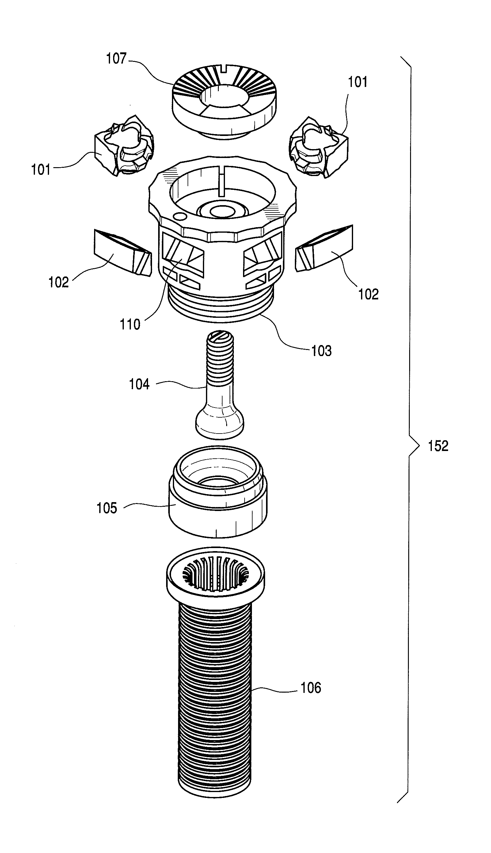
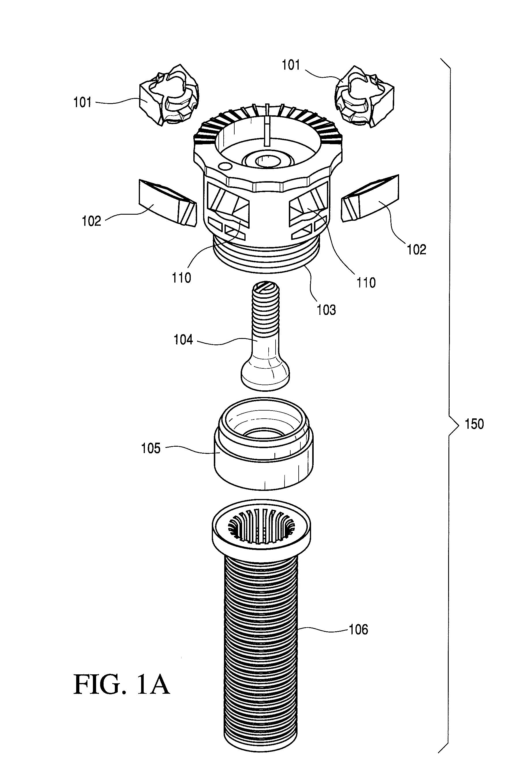
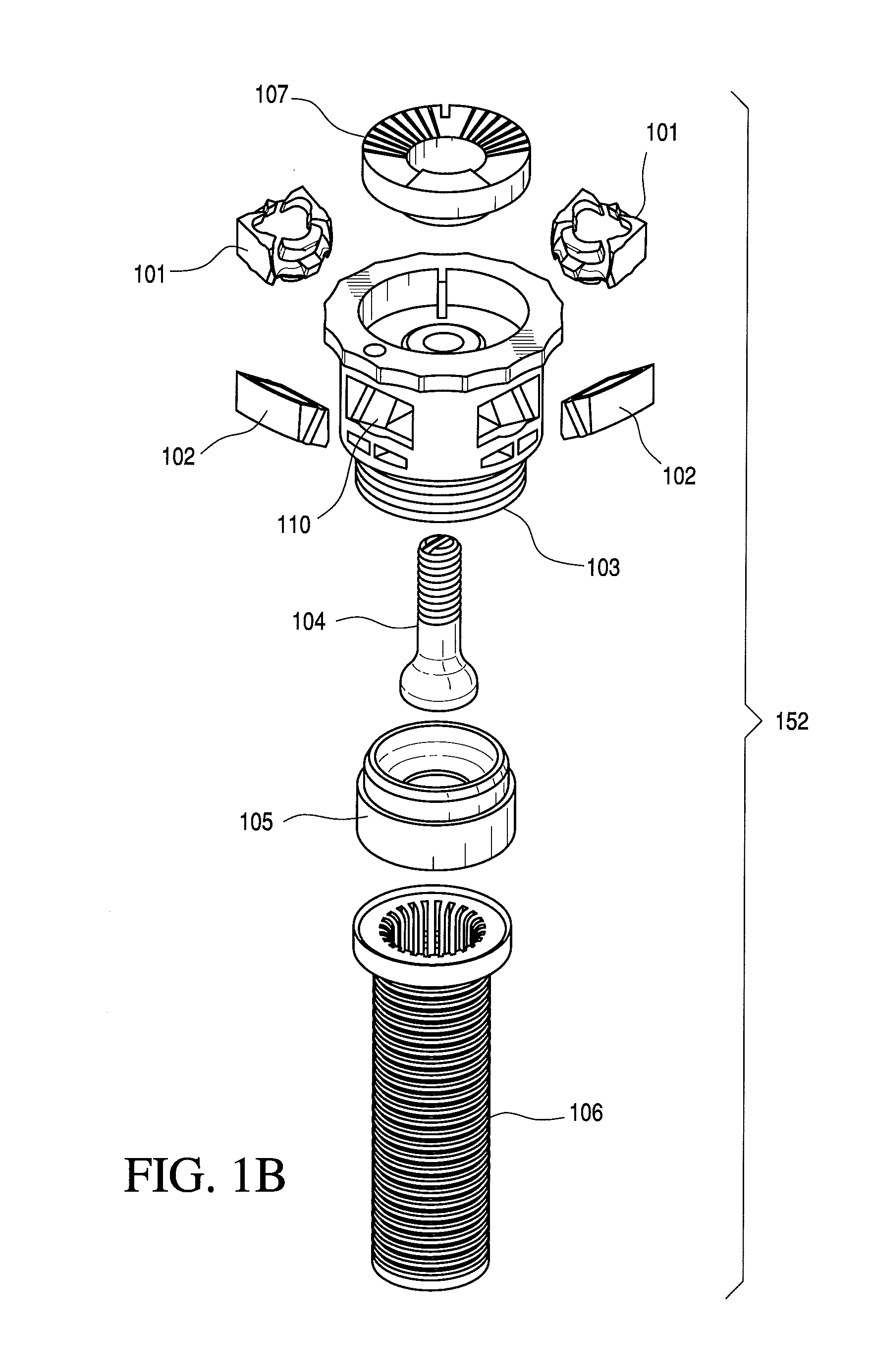
[0073]Turning now to FIGS. 1A-18, in accordance with the present invention, a long throw distance pop-up sprinkler head or irrigation nozzle assembly 150 achieves long throw distance using “fixed” components with no oscillating or rotating parts. While the illustrated embodiment is a “pop-up” sprinkler head, adapted to function is an industry-standard form factor, other configurations are readily adapted from these examples. For example, the nozzle assembly 150 is ready altered to be “fixed”, and so need not include the “pop-up” features. As noted above, the nozzle assemblies described below are each configured with a housing that will work in standard sprinkler systems, in place of standard fixed or pop-up sprinkler heads. In the illustrated embodiments (e.g., FIGS. 1A-20), the housing (e.g., 103) has a substantially cylindrical exterior sidewall with an outside diameter of 19.18 mm, an axial length of 11.18 mm, terminates distally in an transverse flange having an outside diameter...


PUM


Abstract

A long throw Pop-Up Irrigation Nozzle assembly has no oscillating or rotating parts and includes a cylindrical body having a fluid inlet and a sidewall defining at least one fluidic circuit configured to generate a selected spray pattern when irrigation fluid flows through the body. In order to throw long distance, droplet velocity, droplet size and droplet initial aim angle determine the throw to provide a low precipitation rate (“PR”) for fluidic sprays. The nozzle assembly and method of the present invention achieve a PR of 1 in / hr or less and good spray distribution with a scheduling coefficient (“SC”) of about 1.5 without utilizing any moving components to provide a significantly more cost effective nozzle assembly, as compared to prior art rotator nozzles.

Description

PRIORITY CLAIMS AND REFERENCE TO RELATED APPLICATIONS[0001]This application is a Divisional application for copending U.S. non-provisional application Ser. No. 12 / 314,242. This application claims priority to related and commonly owned U.S. provisional patent application No. 61 / 012,200, filed Dec. 7, 2007, the entire disclosure of which is incorporated herein by reference. This application also claims priority to related and commonly owned U.S. provisional patent application Nos. 61 / 136,744 and 61 / 136,745, each filed Sep. 30, 2008, the entire disclosures of which are also incorporated herein by reference.BACKGROUND OF THE INVENTION[0002]1. Field of the Invention[0003]The present invention relates to irrigation nozzles or sprinkler heads, as used in automatic lawn sprinkling and other irrigation systems.[0004]2. Discussion of Related Art[0005]In-ground irrigation nozzles (e.g., sprinkler heads) have been on the market for many years and come in many different configurations for deposi...

Claims


Application Information

Patent Timeline
Patent Type & Authority Applications(United States)
IPC IPC(8): B05B1/02A01G25/00B05B15/10
CPCB05B1/02B05B15/10A01G25/00B05B1/08B05B1/14B05B1/304B05B15/74B05B15/65B05B15/70
Inventor RUSSELL, GREGORYGOPALAN, SHRIDHARSOUTH, CHRISTOPHERHESTER, RUSSELLKOEHLER, ERICALLEN, KERRIESRIDHARA, SRINIVASAIAH
Owner DLHBOWLES INC
Learn More