Cooling module for vehicle

a technology for cooling modules and vehicles, applied in the direction of machines/engines, mechanical equipment, transportation and packaging, etc., can solve the problems of increasing operating power, complicated layout of each piping that connects the operating system with the air conditioning system, and increasing the cooling performance of the vehicle. , to achieve the effect of saving the power consumption of water pumps and cooling fans, preventing cooling performance differences, and improving cooling performan

Inactive Publication Date: 2015-04-16
HYUNDAI MOTOR CO LTD
View PDF6 Cites 9 Cited by
  • Summary
  • Abstract
  • Description
  • Claims
  • Application Information

AI Technical Summary

Benefits of technology

[0014]Various aspects of the present invention provide for a cooling module for a vehicle having advantages of dividing a condenser into a water cooled type and an air cooled type, disposing each condenser, a radiator for electric devices, and a radiator for a stack according to a amount of heat transfer and a driving temperature as one package in an air conditioning system in such a way that cooling performance of a vehicle and cooling / heating performance are improved, cooling performance difference is prevented, consuming power of a water pump and a cooling fan are saved, travel distance is increased, and capacity of cooling fan and each radiator are reduced to save manufacturing cost.
[0025]As described above, in a cooling module for a vehicle according to various aspects of the present invention, a condenser is divided into a water cooled type of a first condenser and an air cooled type of a second condenser, each condenser, a radiator for electric devices, and a radiator for a stack are disposed according to a amount of heat transfer and a driving temperature as one package in an air conditioning system, and therefore there are effects that cooling performance of a vehicle and cooling / heating performance are improved, cooling performance difference is prevented, consuming power of a water pump and a cooling fan are saved, travel distance is increased, and capacity of cooling fan and each radiator are reduced to save manufacturing cost.
[0026]Also, an air conditioning system and a cooling system are unified to form one module, and therefore a package is reduced, capacity of each radiator can be reduced, and manufacturing cost is saved.
[0027]Also, when it is disposed at a front side of an engine compartment, a mounting space is minimized, and therefore there is an effect that space efficiency is improved in a vehicle.
[0028]Also, a layout of piping is simple, and therefore there are effects that piping length through which refrigerant and coolant flow is reduced, flowing resistance of each operating fluid is reduced, and flowing amount is increased.

Problems solved by technology

However, in a cooling module of a cooling system for a conventional environmentally-friendly vehicle, a radiator for electric devices, a radiator for a stack, and an air conditioning condenser are disposed in a front / rear direction of a vehicle and a capacity of a radiator for a stack has to be increased to secure cooling performance of a fuel cell stack, and therefore the configuration of the cooling module becomes complicated and there is a problem that the layout of each piping that connects the operating system with the air conditioning system is complicated.
Also, when a radiator for electric devices, a radiator for a stack, and an air condenser are disposed from a front side to rear side direction, it is hard to secure a space for mounting a cooling module between an engine room and a bumper and an amount of heat transfer and an operating temperature of each radiator and an air condenser are different from each other, thus, when they are cooled by cooling fan and traveling wind, the cooling system can overcool refrigerant or undercool, and a cooling fan and a water pump are operated based on the system that a cooling capacity is low, and therefore there is a problem that the operating power is increased and traveling distance is decreased.

Method used


Image

  • Cooling module for vehicle
  • Cooling module for vehicle
  • Cooling module for vehicle

Examples


Embodiment Construction

[0035]Reference will now be made in detail to various embodiments of the present invention(s), examples of which are illustrated in the accompanying drawings and described below. While the invention(s) will be described in conjunction with exemplary embodiments, it will be understood that present description is not intended to limit the invention(s) to those exemplary embodiments. On the contrary, the invention(s) is / are intended to cover not only the exemplary embodiments, but also various alternatives, modifications, equivalents and other embodiments, which may be included within the spirit and scope of the invention as defined by the appended claims.

[0036]In the specification, unless explicitly described to the contrary, the word “comprise” and variations such as “comprises” or “comprising” will be understood to imply the inclusion of stated elements but not the exclusion of any other elements.

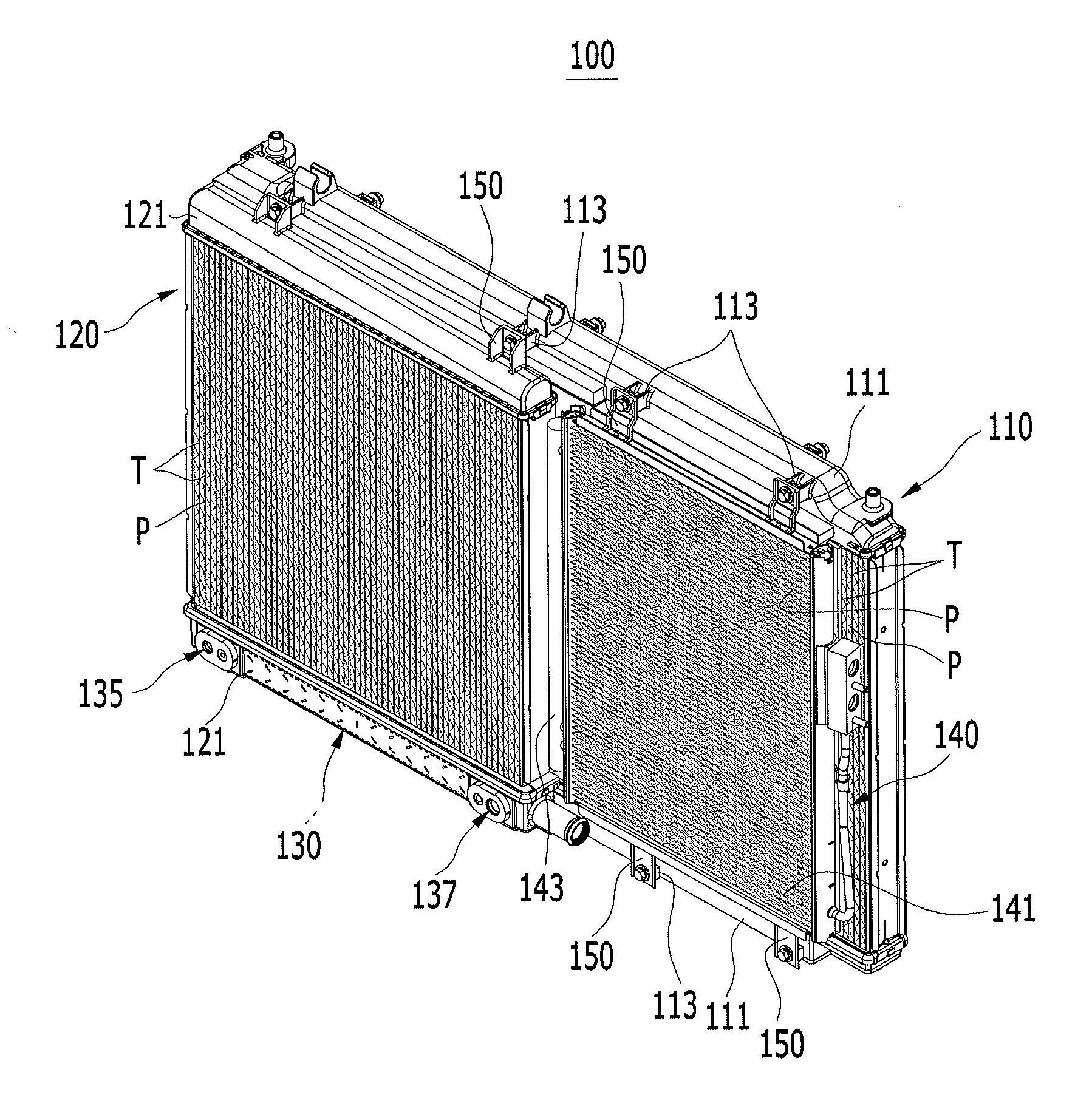
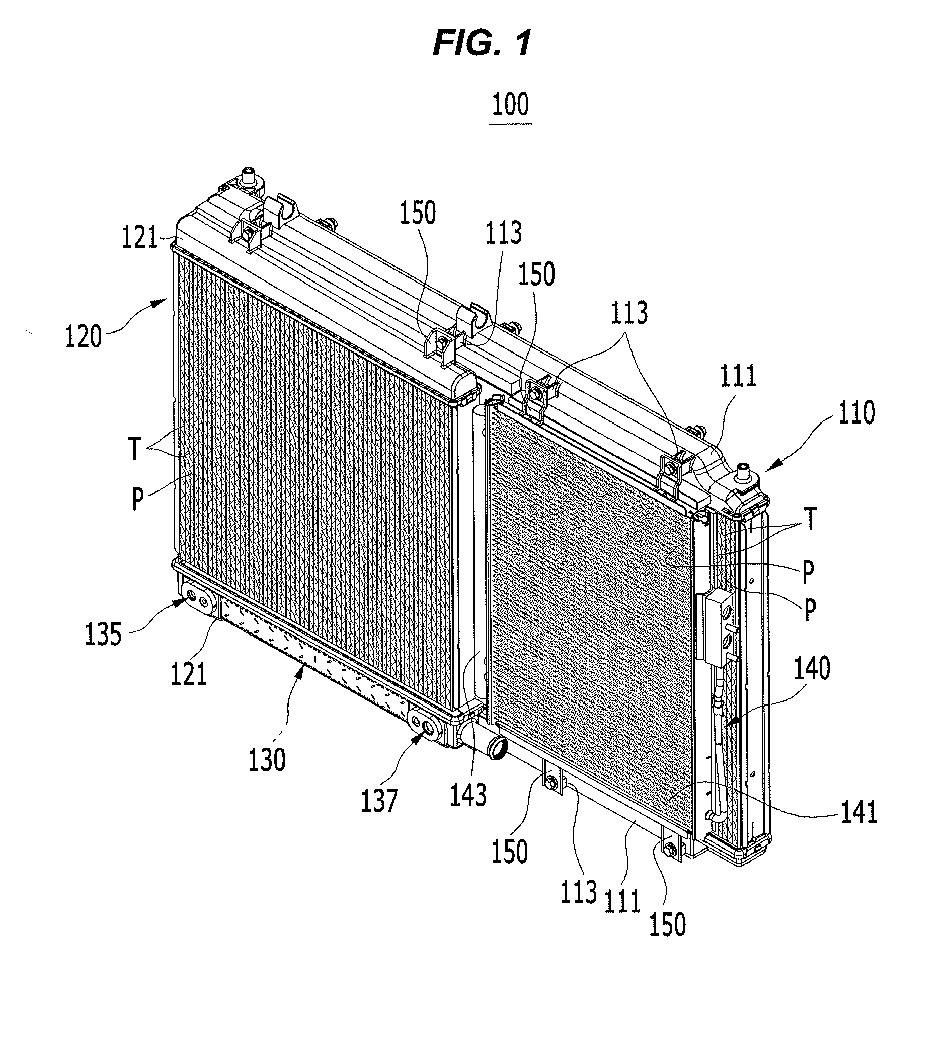
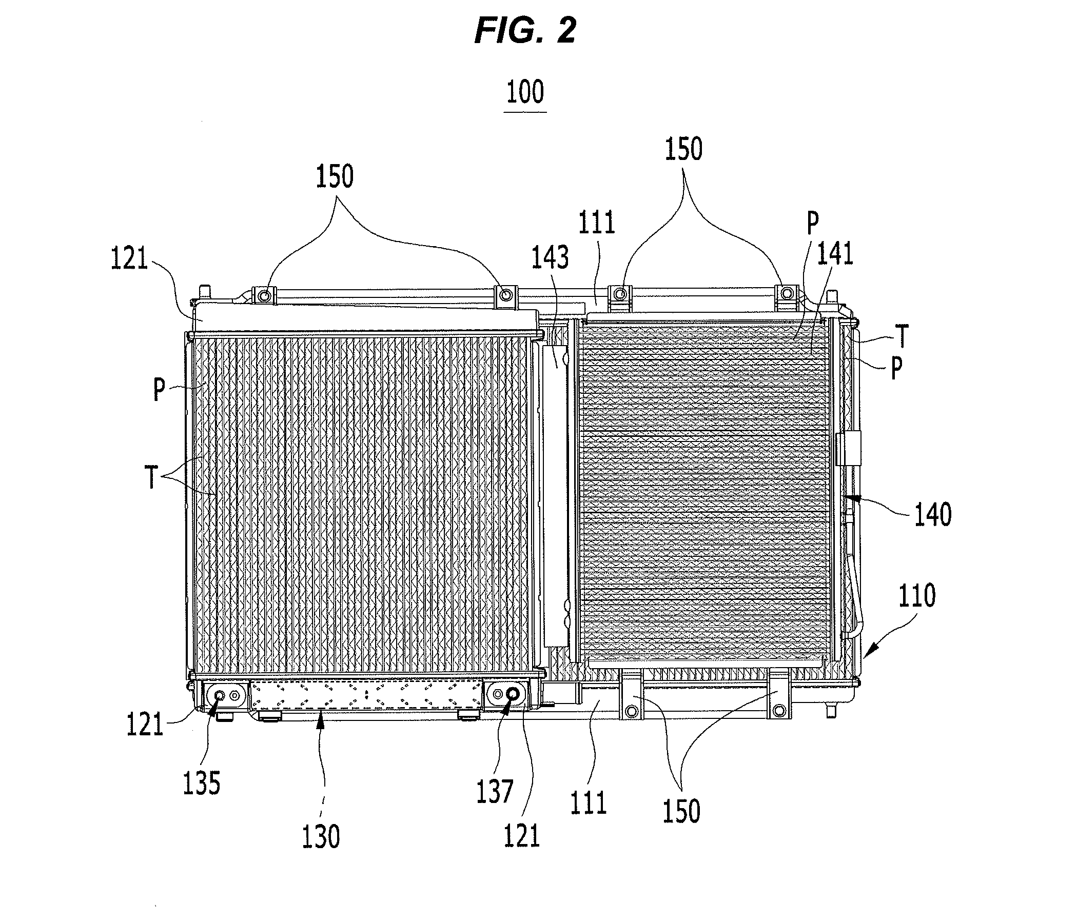
[0037]FIG. 2 is a projective front view of a cooling module for a vehicle according to ...


PUM


Abstract

A cooling module for a vehicle connected to an operating system and an air conditioning system. The cooling module may include a radiator for a stack that is disposed at a rear side based on a front / rear direction of a vehicle, a radiator for electric devices that is disposed at one side based on a width direction of a vehicle at a front side of the radiator for a stack, a first condenser that is disposed inside a header tank of the radiator for electric devices to condense refrigerant as a first condensing process, and a second condenser that is disposed at the other side based on a width direction of a vehicle at a front side of the radiator for a stack and is connected to the first condenser to condense the refrigerant that is exhausted from the first condenser as a second condensing process.

Description

CROSS-REFERENCE TO RELATED APPLICATION[0001]The present application claims priority of Korean Patent Application Number 10-2013-0122240 filed Oct. 14, 2013, the entire contents of which application is incorporated herein for all purposes by this reference.BACKGROUND OF INVENTION[0002]1. Field of Invention[0003]The present invention is related to a cooling module for a vehicle. More particularly, the present invention relates to a cooling module for a vehicle that a condenser of an air conditioning system is separately disposed in an electric vehicle, each condenser, a radiator for electric devices, and a radiator for a stack are disposed depending on amount of heat transfer and operating temperature, and a cooling performance of a vehicle is improved such that a travel distance is extended, and a heating / cooling performance and a package are improved.[0004]2. Description of Related Art[0005]Recently, energy efficiency and environmental pollution are of increasing concern, and enviro...

Claims


Application Information

Patent Timeline
Patent Type & Authority Applications(United States)
IPC IPC(8): F01P3/12
CPCF01P3/12F01P3/18F01P2003/182
Inventor KIM, JAE YEONKIM, SU WHANCHO, WAN JE
Owner HYUNDAI MOTOR CO LTD
Why Eureka
Try Eureka