Shackle assembly

a technology of shackles and components, applied in the direction of shackles, load-engaging elements, chain elements, etc., can solve the problems of inability to meet the needs of users, inability to use safe, cumbersome and undesirable, etc., and achieve the effect of improving the coupling

Active Publication Date: 2015-04-16
IHC HOLLAND NV
View PDF0 Cites 2 Cited by
  • Summary
  • Abstract
  • Description
  • Claims
  • Application Information

AI Technical Summary

Benefits of technology

[0027]In an embodiment of the invention, at least one of both legs is on both sides provided with a said mounting plate. This improves the coupling between the driving device and the shackle.

Problems solved by technology

Under circumstances this shackle assembly of WO 2006 / 055581 A2 is unpractical and not safe in use.
The nut is screwed to the bolt by an additional robot distinct from the shackle connecting device, which additional robot is costly, cumbersome and undesirable.

Method used


Image

  • Shackle assembly
  • Shackle assembly
  • Shackle assembly

Examples


Embodiment Construction

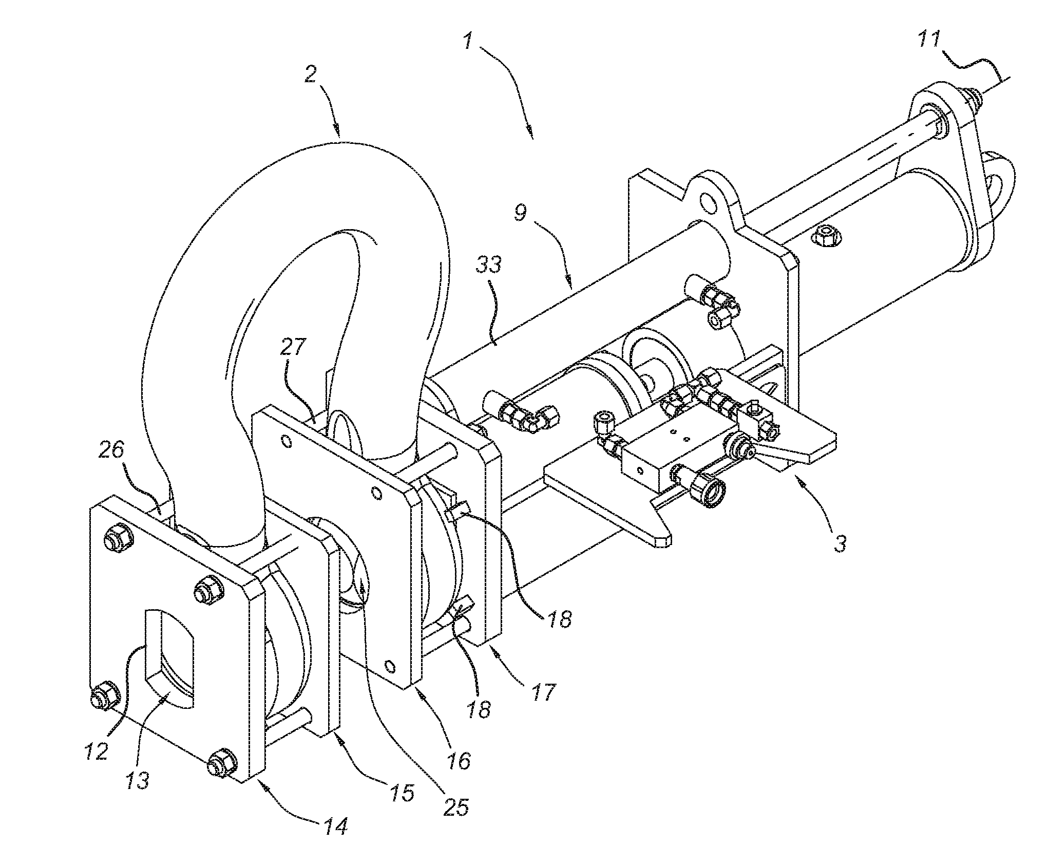
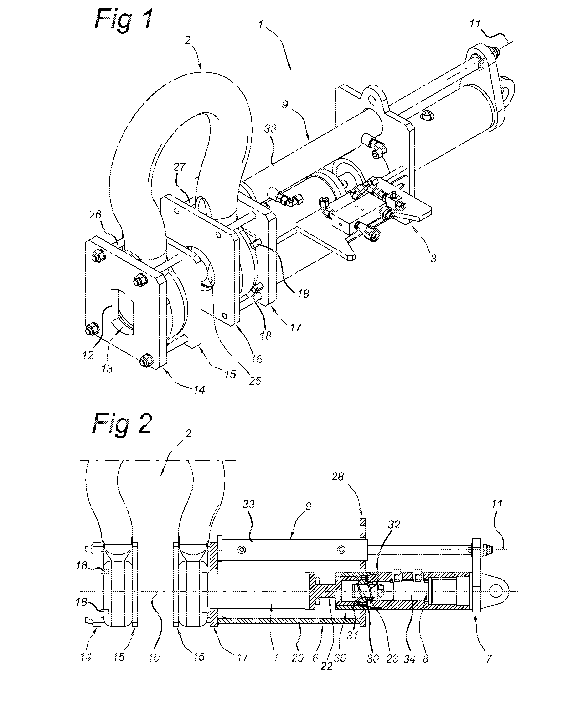
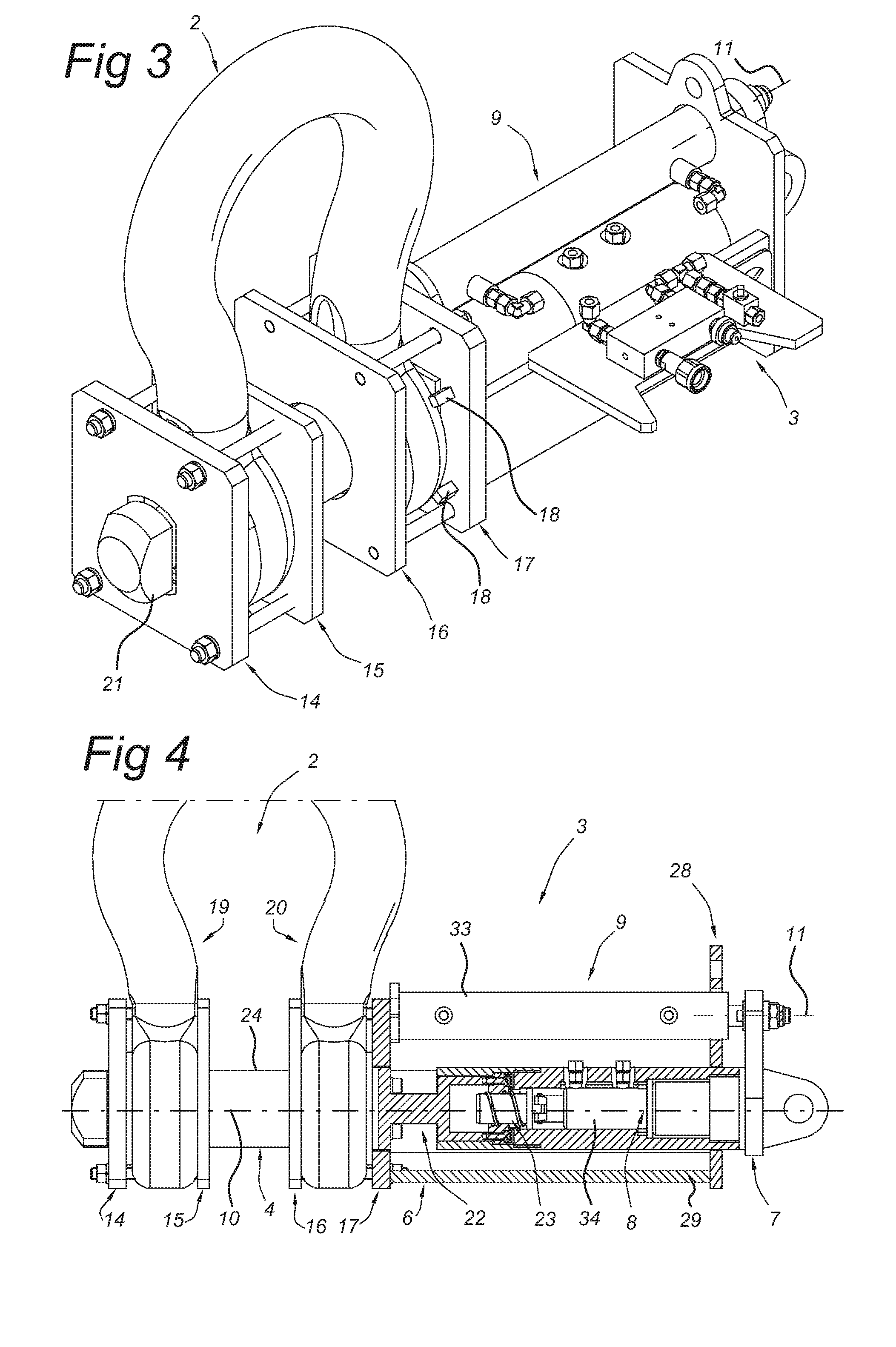
[0040]An embodiment of the shackle assembly is described below, referring to FIG. 1-6.

[0041]The shackle assembly 1 comprises a shackle 2 and a driving device 9 coupled with the shackle for driving a shackle bolt 4. The shackle 2 has a U-shape with a first and second leg 19, 20. The second leg 20 faces the driving device 9 and is coupled with the driving device 9. Both the first and second leg are provided with a recess or opening 13, 25 for passing the shackle bolt 4 having a bolt outside surface 24 there through.

[0042]The shackle assembly 1 comprises means for rotating the shackle bolt 4 around the longitudinal axis 10 of the shackle bolt for moving the locking means 21. In this case, these means include a further driving device 8, here a hydraulic cylinder, and means for transforming a shackle bolt driving force along the longitudinal axis 10 of the shackle bolt 4, into rotation of the shackle bolt 4 around the longitudinal axis of the shackle bolt. The shackle bolt driving force ...


PUM


Abstract

A shackle assembly including a shackle and a driving device coupled with the shackle for driving a bolt system, which driving device is arranged to reciprocate the bolt system along the longitudinal axis of the bolt system between a shackle installing position and a shackle releasing position, wherein the bolt system includes a locking unit for locking the bolt system in its shackle installing position, and wherein the shackle assembly includes elements for transforming reciprocating movement of the bolt system into rotation of the locking unit around the longitudinal axis of the bolt system between a bolt locking position and a bolt release position of the locking unit.

Description

BACKGROUND[0001]The present invention relates to a shackle assembly comprising a shackle and a driving device coupled with the shackle for reciprocating a shackle bolt along the longitudinal axis of the shackle bolt between a shackle installed position and a shackle released position. The shackle assembly is in particular suitable for use in offshore and subsea operations which requires high allowable load and stringent safety standards.[0002]Such a shackle assembly is known from WO 2006 / 055581 A2 which relates to a shackle assembly and a method for installing and / or releasing the shackle assembly subsea using a shackle pin pulling tool. This tool is separate from the shackle body which allows multiple subsea shackles to be operated with the use of a single hydraulic shackle pin removal or installation tool. Under circumstances this shackle assembly of WO 2006 / 055581 A2 is unpractical and not safe in use.[0003]WO2011 / 117446 relates to a shackle connecting device which is intended to...

Claims


Application Information

Patent Timeline
Patent Type & Authority Applications(United States)
IPC IPC(8): B63C11/52F16G15/06
CPCB66C1/34F16G15/04B63C11/52F16G15/06
Inventor VAN STEIJN, THEODORUS GERARDUS WILHELMUSMULDERIJ, KLAAS-JAN
Owner IHC HOLLAND NV
Why Eureka
Try Eureka