
Method and apparatus for plasma ignition in high vacuum chambers

Inactive Publication Date: 2015-04-09
XEI SCI
View PDF19 Cites 14 Cited by
  • Summary
  • Abstract
  • Description
  • Claims
  • Application Information

AI Technical Summary

Benefits of technology

The present invention provides a way to ignite a plasma in a high vacuum chamber when the gas density is not high enough to allow for the plasma's conductivity. The method involves applying a finite amount of gas into a small plasma chamber while also applying power to the chamber. This results in a higher pressure plasma ignition, with the vacuum chamber maintaining a lower pressure due to a small leak or flow of working gas. This method simplifies plasma ignition in high vacuum chambers and improves the efficiency of the plasma system.

Problems solved by technology

However these pumps have trouble achieving vacuums below 1 Pa.
At these low pressures, it is difficult to ignite plasmas in part because of the reduced density of the gas and lack of free electrons.
Plasmas not aided by magnetic fields to confine electrons can operate in the upper ends of this pressure range but are difficult to ignite.
To ignite plasma in mid vacuum, a source of free electrons, an ionization source, a pressure change, or a high electric field is needed, necessitating expensive additions to the instrument.
It is very difficult to ignite the plasma below 10 Pa pressure consistently without an enhancement method.
they can overheat or suffer mechanical stress if sudden additional gas load is encountered.

Method used


Image

  • Method and apparatus for plasma ignition in high vacuum chambers
  • Method and apparatus for plasma ignition in high vacuum chambers
  • Method and apparatus for plasma ignition in high vacuum chambers

Examples


Embodiment Construction

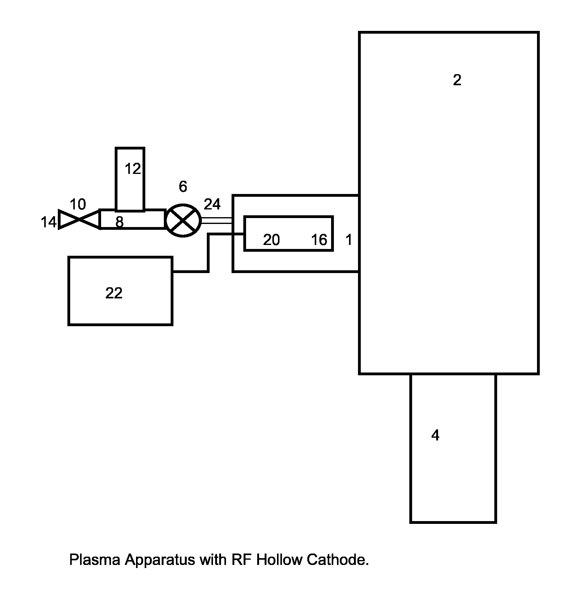
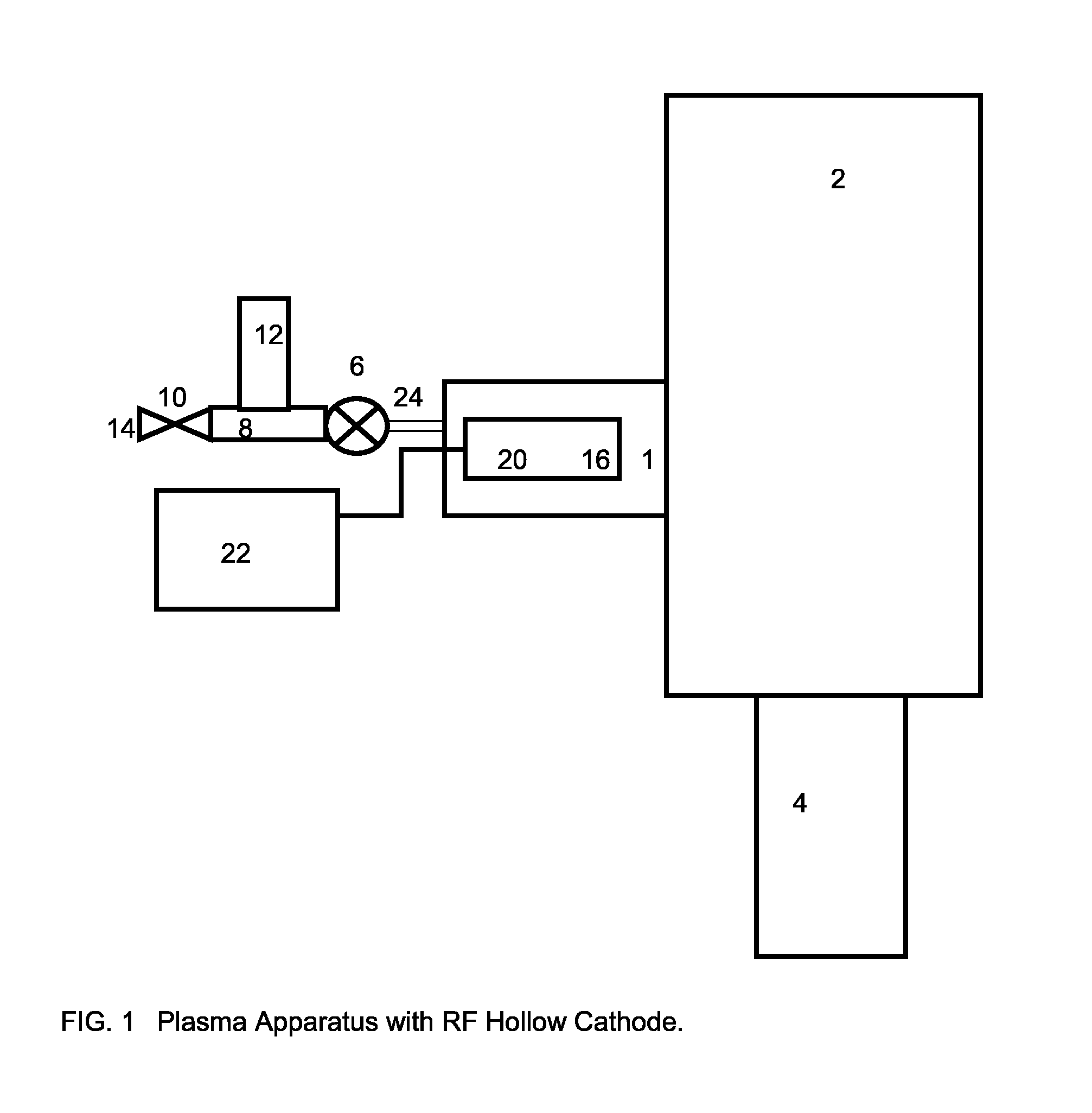
[0043]FIG. 1 schematically illustrates the apparatus according to the present invention. A small plasma chamber 1 is attached in fluid communication with the main vacuum chamber 2 of an analytical instrument. As mentioned, the present invention is particularly concerned with the specimen chamber of an electron microscope or similar analytical instrument using an electron beam such as a scanning electron microprobe instrument or focused ion beam instrument. Accordingly, main vacuum chamber 2 is the sample chamber of such an instrument.

[0044]Main vacuum chamber 2 is connected to a turbo-molecular pump (TMP) 4, which is used to evacuate or draw a vacuum in chamber 2. An electronically controlled open / close valve 6 is connected to small plasma chamber 1 via a gas valve connector 24 at the end opposite main vacuum chamber 2. Valve 6 controls (in a binary fashion) the flow of a gas into small plasma chamber 1 from a gas manifold 8 and hollow cylindrical gas buffer chamber 12, which is in ...


PUM


Abstract

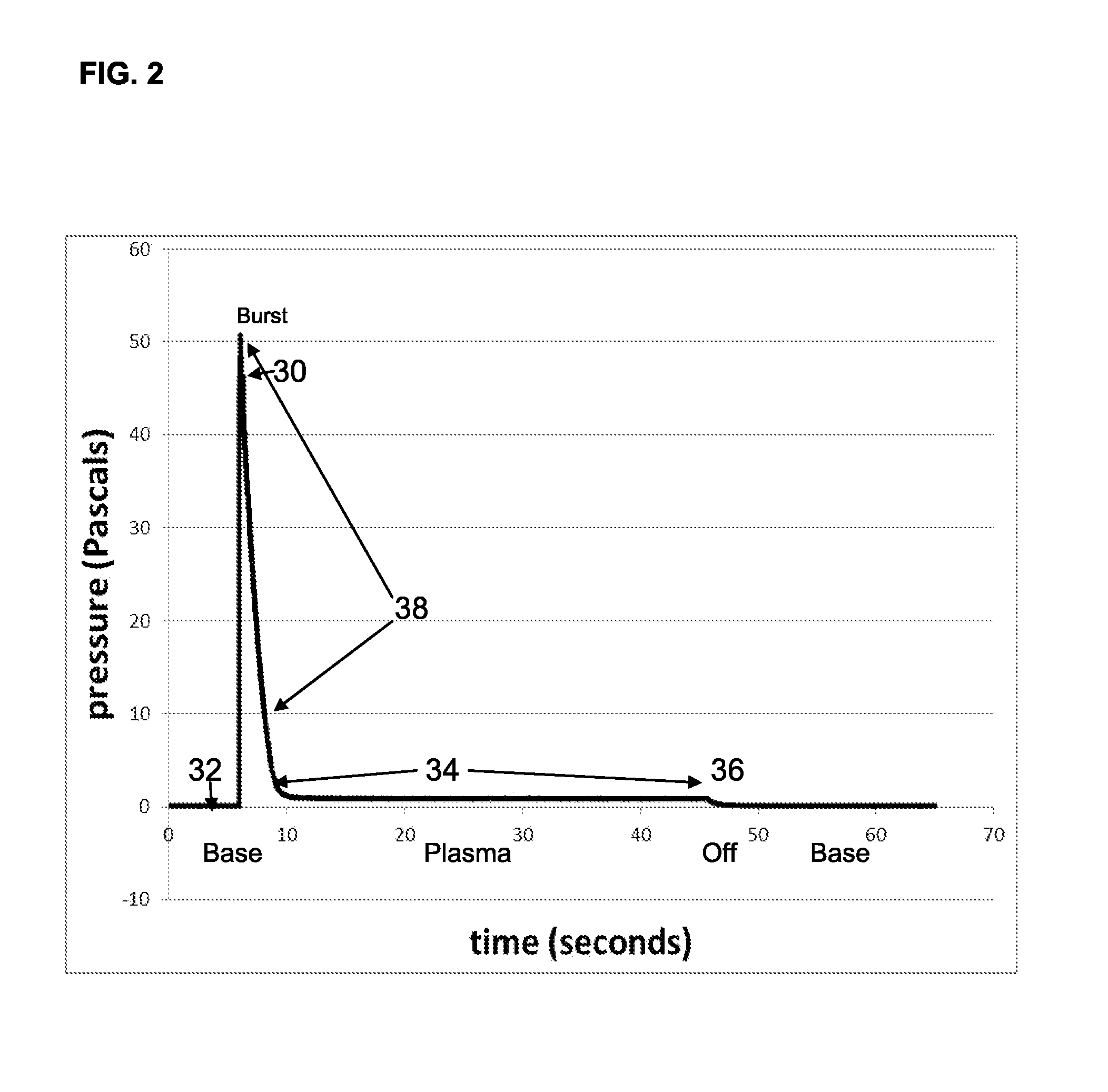
A plasma process method and apparatus for use with a vacuum instrument having a vacuum chamber evacuated by an oil free high vacuum pump to a base pressure below about 1 Pa. A gas buffer chamber in fluid communication with the plasma chamber, the gas buffer chamber having a volume about 1 / 500 to 1 / 2000 of the volume of the vacuum chamber. A valve between the plasma chamber and the gas chamber permits flow between the gas chamber and the plasma chamber, wherein, upon opening the valve, gas is admitted into the plasma chamber and pressure in the plasma chamber rises temporarily to between about 10 and about 200 Pa and plasma ignition can be obtained when the plasma excitation device is energized simultaneously. A flow restriction between the gas source and the gas chamber has a maximum flow rate therethrough of about 25 sccm. (standard cubic centimeters per minute) or less so that pressure in the plasma chamber remains between about 1 and about 7 Pa after plasma ignition to maintain plasma conduction and to avoid overloading or heating of the high vacuum pump.

Description

BACKGROUND OF THE INVENTION[0001]1. Field of Invention[0002]The present invention relates to a new method and apparatus to quickly ignite and start a non-equilibrium gas plasma. More particularly, the present invention is directed to such a method and apparatus for use in a high vacuum system that is pumped by a turbo-molecular pump and then after ignition maintains a low flow of working gas through the plasma at rate that does not load and overheat the turbo-molecular pump. The resulting plasma is used to produce from the working gas active species such as neutral radicals, metastables, ions, free electrons, and UV and visible light while the turbo molecular pump continues to operate.[0003]2. Summary of Prior Art[0004]Plasma or a gas excited into electrically conductive ions and electrons is quite useful in plasma processing, producing excited species, producing light, and cleaning hydrocarbon and other contaminants from surfaces of vacuum instruments. It is known that at low vacuu...

Claims


Application Information

Patent Timeline
IPC IPC(8): H01J37/32
CPCH01J37/32449H01J2237/335H01J37/32082H01J37/32596H01J37/32357H01J37/32862
Inventor VANE, RONALD A.
Owner XEI SCI
Learn More