Signal processing system and signal processing method
a signal processing system and signal processing technology, applied in the field of signal processing system and signal processing method, can solve the problems of limiting the optimization of cell design and the maximization of system capacity, and achieve the effect of maximizing the diversity effect of the terminal, improving the performance of the terminal, and improving the channel prediction performance of the terminal located within the cell
- Summary
- Abstract
- Description
- Claims
- Application Information
AI Technical Summary
Benefits of technology
Problems solved by technology
Method used
Image
Examples
first embodiment
[0066]First, in the present invention, a case in which a terminal is adjacent to a cell in a cell boundary area will be described.
[0067]FIG. 6 is a view illustrating an example of signals transmitted by a plurality of radio units included in a cell according to a first embodiment of the present invention.
[0068]The radio units 111 and 112 according to an embodiment of the present invention each have two antennas to support 2×2 MIMO transmission, and the two antennas transmit the same data as signals having different transmission patterns, respectively. For example, a first antenna may transmit a signal having a first transmission pattern through port #0, and a second antenna may transmit a signal having a second transmission pattern through port #1. Also, the first antenna may transmit a signal having a third transmission pattern through port #7, and the second antenna may transmit a signal having a fourth transmission pattern through port #8.
[0069]Referring to FIG. 6, the radio unit...
second embodiment
[0073]Hereinafter, the present invention will be described in which a terminal is not adjacent to any cells in a cell boundary area (that is, a case in which a terminal is located in a cell overlap region).
[0074]FIG. 7 is a view illustrating an example of signals transmitted by a plurality of radio units included in a cell according to a second embodiment of the present invention.
[0075]Referring to FIG. 7, the radio units 111 and 112 included in the cell 11 whose cell ID is x (e.g., x is a natural number) and the cell 12 whose cell ID is x+3, respectively, transmit data by using a cell-specific RS to the terminals 410 and 420 which are basically located within the cells 11 and 12 and not present in the cell boundary area 13. Namely, the radio units 111 and 112 transmit data signals by using antenna ports #0 and #1. However, to the terminal 440 located in the cell overlap region within the cell boundary region 13, the radio units 111 and 112 transmit the same data through a single an...
third embodiment
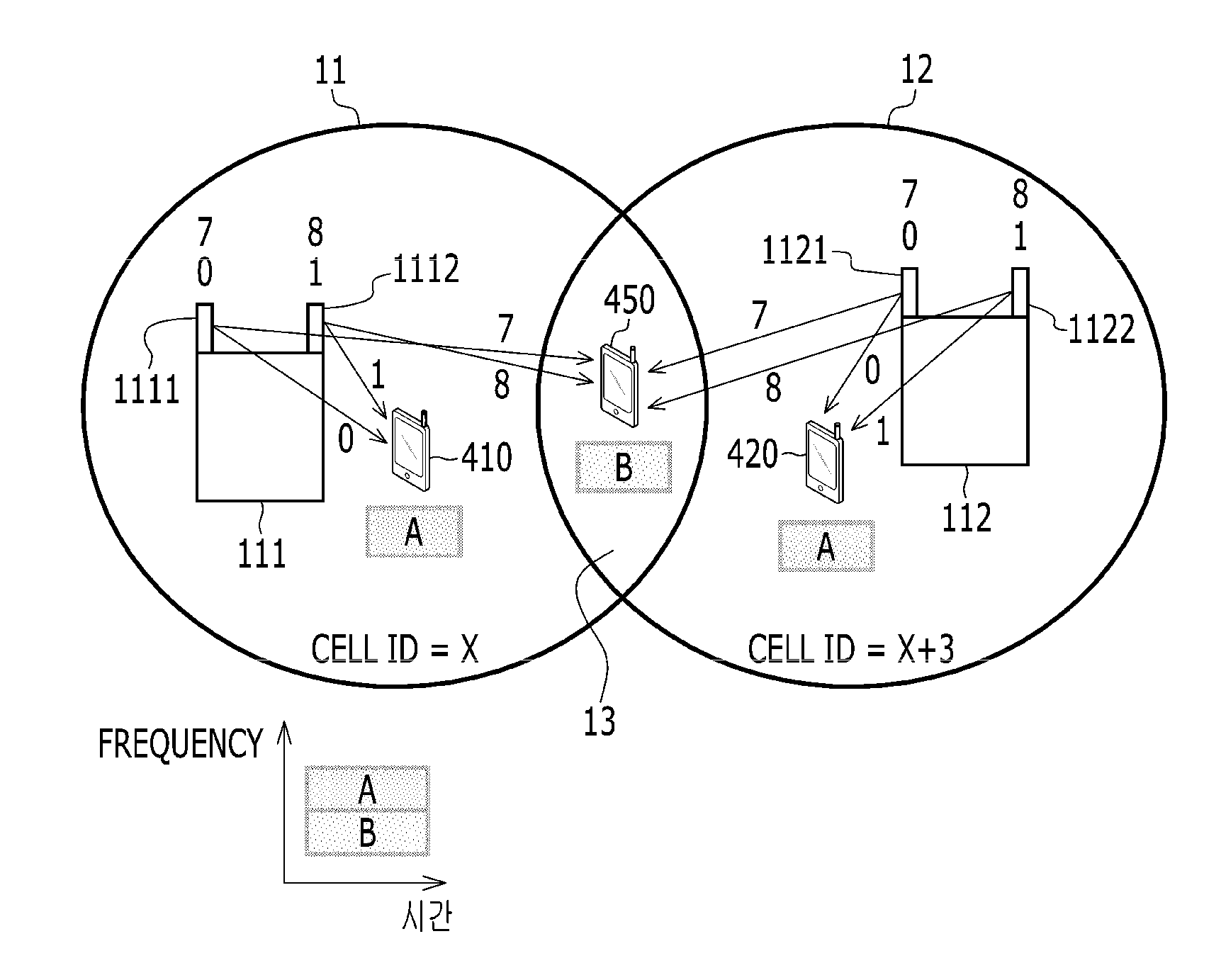
[0082]FIG. 8 is a view illustrating an example of signals transmitted by a plurality of radio units included in a cell according to the present invention.
[0083]In the third embodiment of the present invention, the terminals 410 and 420 located within the cells 11 and 12 are the same as those of the second embodiment, so only components different from those of the second embodiment will be described.
[0084]Referring to FIG. 8, data is transmitted to a terminal 450 located in the cell overlap area within the cell boundary area 13 by using a user-specific RS. In this case, the radio units 111 and 112 transmit the same data through two antenna ports, respectively. That is, the radio units 111 and 112 transmit data signals to the terminal 450 by using both of their respective antenna ports #7 and #8.
[0085]As illustrated in FIG. 8, with respect to the terminal 450 located in the cell overlap area of the boundary area 13, the radio unit 111 of the cell 11 transmits a data signal to the term...
PUM
 Abstract
Description
Claims
Application Information
 - R&D
- Intellectual Property
- Life Sciences
- Materials
- Tech Scout
- Unparalleled Data Quality
- Higher Quality Content
- 60% Fewer Hallucinations
Browse by: Latest US Patents, China's latest patents, Technical Efficacy Thesaurus, Application Domain, Technology Topic, Popular Technical Reports.
© 2025 PatSnap. All rights reserved.Legal|Privacy policy|Modern Slavery Act Transparency Statement|Sitemap|About US| Contact US: help@patsnap.com


