
Rail clip

a technology for rail clips and clips, applied in the field of rail clips, can solve the problems of clip damage, loss of clamping force, serious problems on the track, etc., and achieve the effect of reducing the tendency for the back of the clip to lift up during fitting

Active Publication Date: 2015-03-26
PROGRESS RAIL SERVICES
View PDF17 Cites 2 Cited by
  • Summary
  • Abstract
  • Description
  • Claims
  • Application Information

AI Technical Summary

Benefits of technology

This patent aims to solve the problems of high fitting force and damage to clips during fitting. The invention proposes a clip design with a small radius at the back of the clip which reduces the tendency of the clip to lift up during fitting. A large installed deflection is also recommended to reduce toe load variation. By using these techniques, the clip is made more robust and less prone to damage.

Problems solved by technology

Sometimes the clips become damaged & lose some of their clamping force which allows the rail to “run” in the tie rail seats.
This can then cause serious problems to occur in the track which in the worst case can end in a derailment & train smash.
The main cause of clip damage is the clip fitting machines being out of adjustment and overdriving the clips during track maintenance.
This often happens in tight track curves where the high lateral forces on the rail cause the pads & insulators to wear so the clips have to be frequently removed for renewing these parts.
This frequent removal & refitting of the clips increases the chance of an out of adjustment fitting machine damaging the clips.
This is a considerable expense which should not be necessary since with many clip designs the clips have an indefinitely long fatigue life and do not “wear out”.
The replacement need is solely caused by clip fitting machine damage.

Method used


Image

  • Rail clip
  • Rail clip
  • Rail clip

Examples


Embodiment Construction

[0033]Preferred embodiments of the invention will now be described with reference to the drawings in which

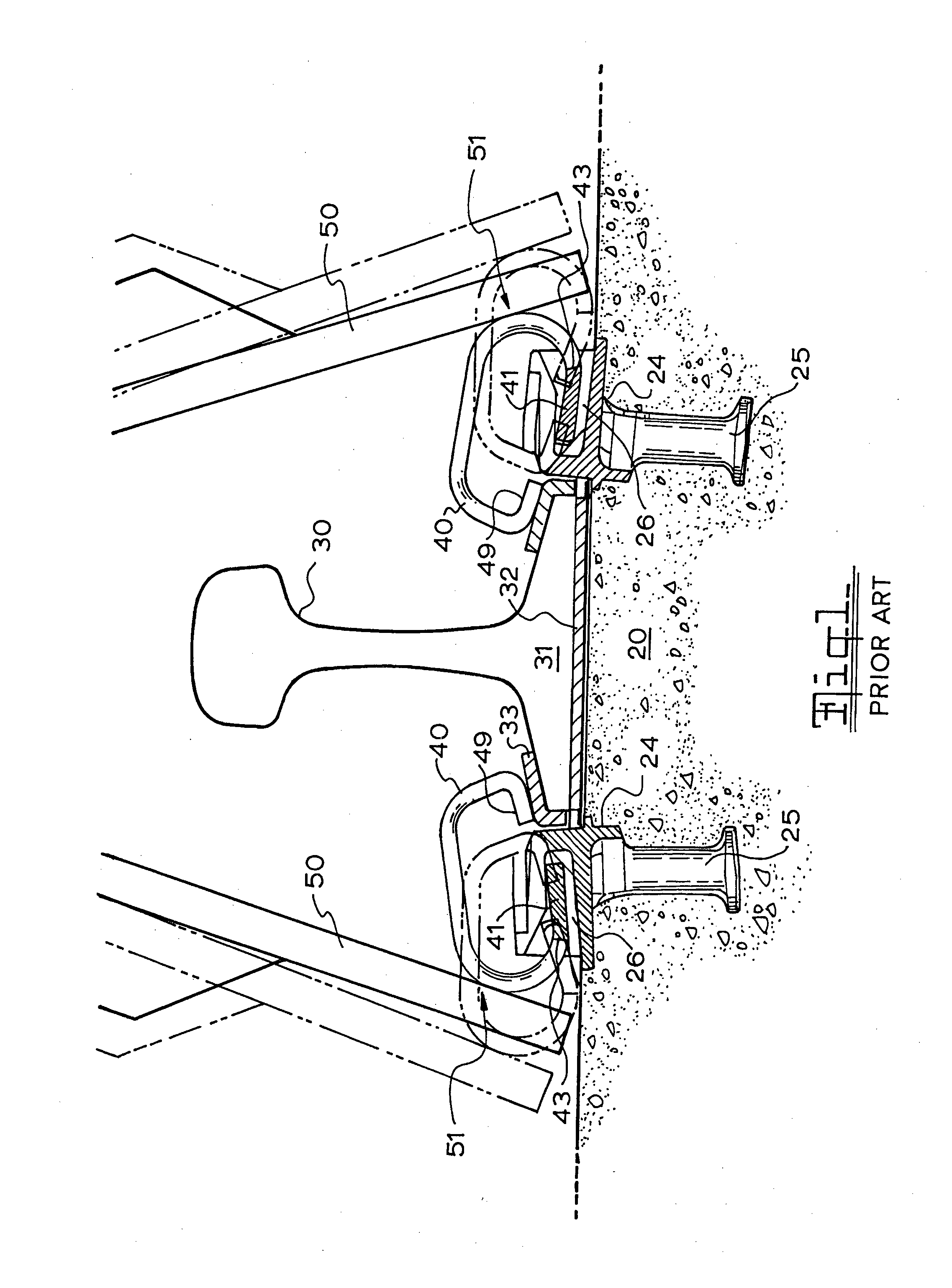
[0034]FIG. 1 is a cross sectional view of a prior art rail seat using a prior art Young clip showing the clip in a preload and a load position Z;

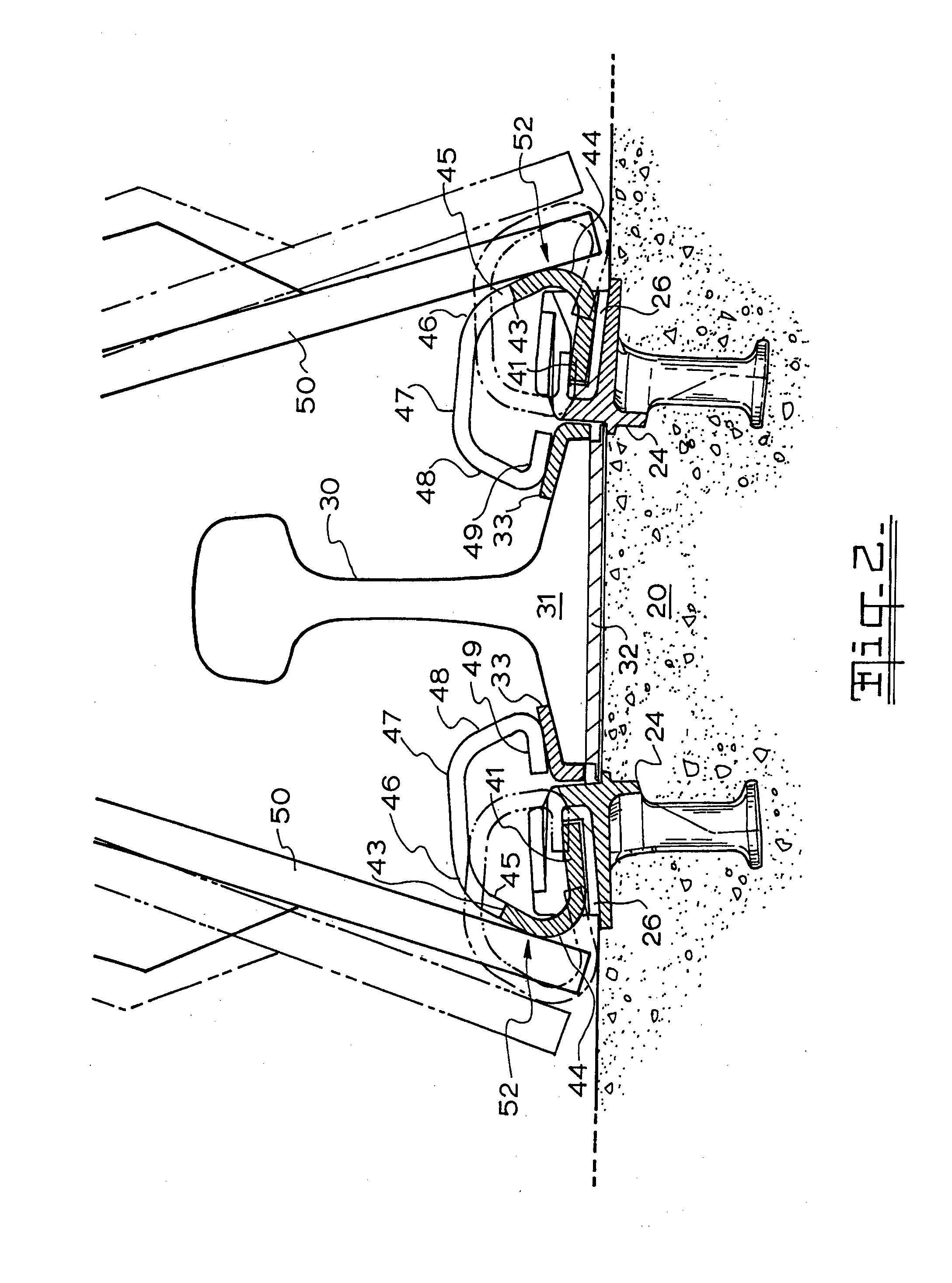
[0035]FIG. 2 is a cross sectional view of a rail seat using a rail clip according to the present invention showing the clip in a preload and a load position;

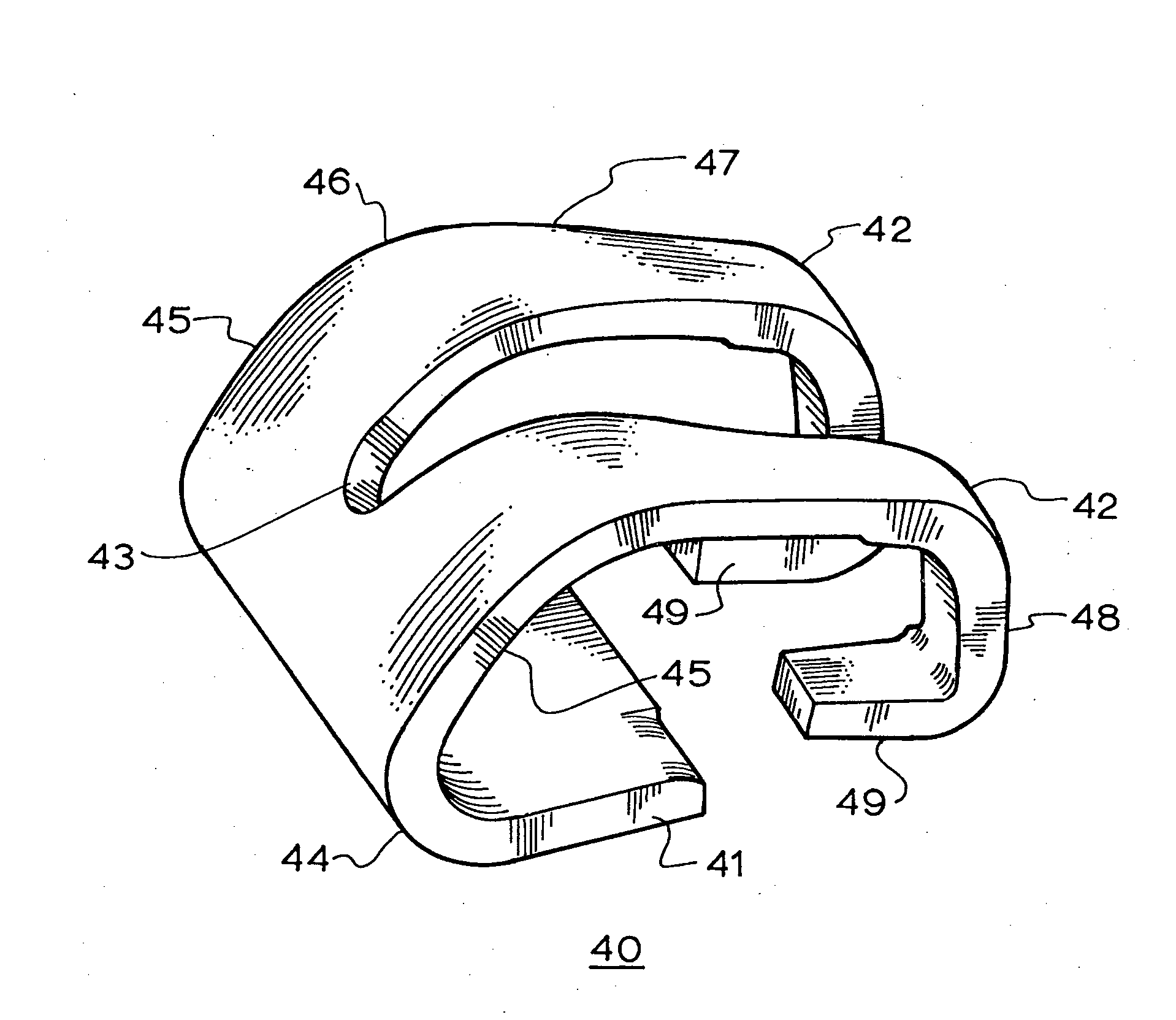
[0036]FIG. 3 is a perspective view of a rail clip according to the present invention;

[0037]FIG. 4 illustrates the deflection of the clip during manufacture and use.

[0038]FIG. 1 illustrates the prior art Young clip. The components of a typical rail seat are the concrete rail tie 20, the rail 30 with the rail base 31 seating on the rail pad 32 lying between the rail base 31 and the rail tie 20. On either side of the rail 30 are the clip support shoulders 24 with the shoulder legs 25 embedded in the concrete tie 20 and the clip recesses 26 on the surface of the tie. The rail clip 40 ha...


PUM


Abstract

A rail clip for fastening railway rails to rail ties. The clip consists of U -shaped member formed from metal plate having a base with a free end and the other end curving upwards with an internal radius of 18 mm or less and a short straight section followed by a second curve and two tapered arms extending therefrom or beyond the curve, said base adapted to be secured to said tie outwardly spaced from the foot of said rail, said arms being bent downwards in a third curve beyond said base and finally the tip portion of said arms being bent backwards in a forth curve toward and short of said base to form toes which are orientated for contact with the top surface of the rail base such that said arms and toes are deflected upwards relative to said rail to develop downward clamping forces at the said toes which hold the said rail on the said tie to restrain longitudinal, lateral and vertical movement; after the said clip is formed it is hardened and tempered and then cold set by loading it in the same manner as occurs in track but the applied load is increased until the yield is passed and the clip is permanently deformed, the load is then removed & the process is repeated at least once.

Description

BACKGROUND TO THE INVENTION [0001]The main function of modern rail clips is to hold the rail down so firmly that the rail will not become longer when the sun heats the rail & then not become shorter when the rail is subject to colder & freezing conditions. In other words the rail must compress or stretch but not move in the tie rail seats.[0002]Long lengths of welded rail are commonly used so the longitudinal forces in the rail due to temperature change are very high. This means that the rail clips must clamp the rail very tightly.[0003]A popular rail clip is described in U.S. Pat. No. 431,563 (Young).[0004]Sometimes the clips become damaged & lose some of their clamping force which allows the rail to “run” in the tie rail seats. This can then cause serious problems to occur in the track which in the worst case can end in a derailment & train smash.[0005]The main cause of clip damage is the clip fitting machines being out of adjustment and overdriving the clips during track maintena...

Claims


Application Information

Patent Timeline
Patent Type & Authority Applications(United States)
IPC IPC(8): E01B9/02
CPCE01B9/02E01B9/306E01B9/303
Inventor YOUNG, HARTLEY FRANKMEDIAVILLA, JOSE RICARDO
Owner PROGRESS RAIL SERVICES
Learn More