Method and system for introducing make-up flow in an electrospray ion source system

a technology of ion source system and makeup flow, which is applied in the direction of particle separator tube details, separation process, instruments, etc., can solve the problems of spray failure, ineffective monitoring of ion current in this range, and difficult detection of spray failur

Active Publication Date: 2015-03-19
DH TECH DEVMENT PTE
View PDF6 Cites 11 Cited by
  • Summary
  • Abstract
  • Description
  • Claims
  • Application Information

AI Technical Summary

Benefits of technology

[0005]In view of the foregoing, in various embodiments, the applicants' teachings provide an electrospray ion source system for detecting emitter failure. In various embodiments, the system comprises a liquid chromatography column suitable for chromatographic separation of a sample. In various aspects, the column can have an inlet for receiving the sample and an outlet for ejecting the sample. In various embodiments, the system can comprise a make-up flow channel for introducing a make-up flow of liquid to the sample post-column, wherein the make-up flow normalizes the spray current. In various aspects, an electrospray ionization source can be provided having one or more emitter nozzles for receiving the make-up flow containing sample. In various embodiments, there can comprise a power supply for providing a voltage to the one or more emitter nozzles and a measurement device for measuring and monitoring the spray current of the one or more emitter nozzles.

Problems solved by technology

In an electrospray ion source system, oftentimes there can be spontaneous failure of emitters due to the presence of precipitating samples and other fouling agents resulting in spray failure.
Detection of spray failure can be problematic since during an LC run, there is a very large spray current range, for example, spanning from 1 nA to 150 nA from the beginning of a gradient to the end of the gradient making monitoring the ion current in this range ineffective.
But, oftentimes separating closely related ions, such as isoforms and isomers can be difficult.

Method used


Image

  • Method and system for introducing make-up flow in an electrospray ion source system
  • Method and system for introducing make-up flow in an electrospray ion source system
  • Method and system for introducing make-up flow in an electrospray ion source system

Examples


experimental example

[0150]Materials. All three isomers of aminobenzoic acid (2-, 3-, and 4-aminobenzoic acid) and deuterated water (100%) were obtained from Sigma-Aldrich (St. Louis, Mo.) and were used without further purification. HPLC-grade acetonitrile was purchased from Caledon Laboratory Chemicals (Georgetown, ON), and HPLC-grade methanol was purchased from J.T. Baker (Avantor Performance Chemicals, Center Valley, Pa.); these solvents were also used without further purification. Distilled deionized water (15 MΩ) was produced in-house using a Millipore (Billerica, Mass.) Integral 10 water purification system.

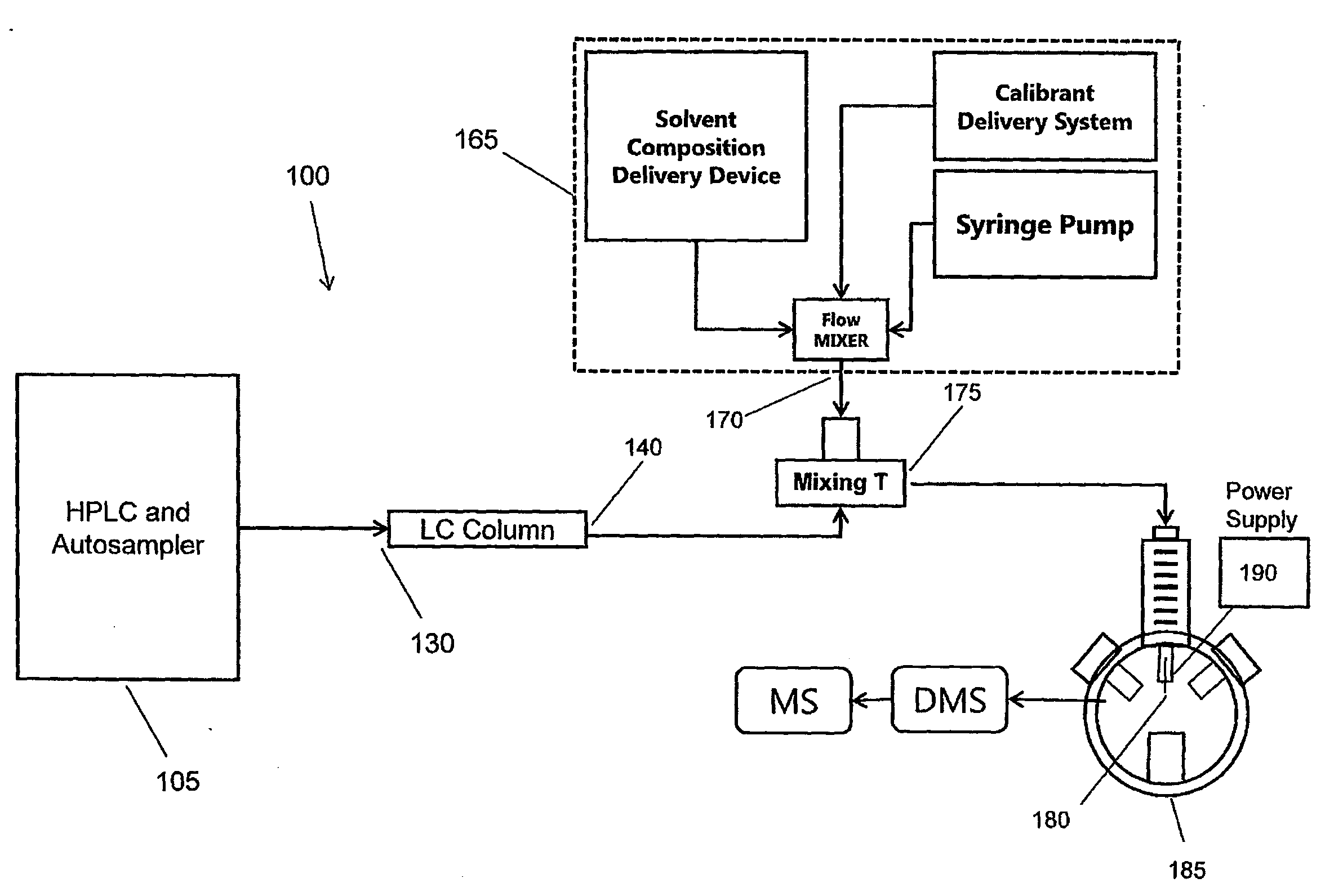
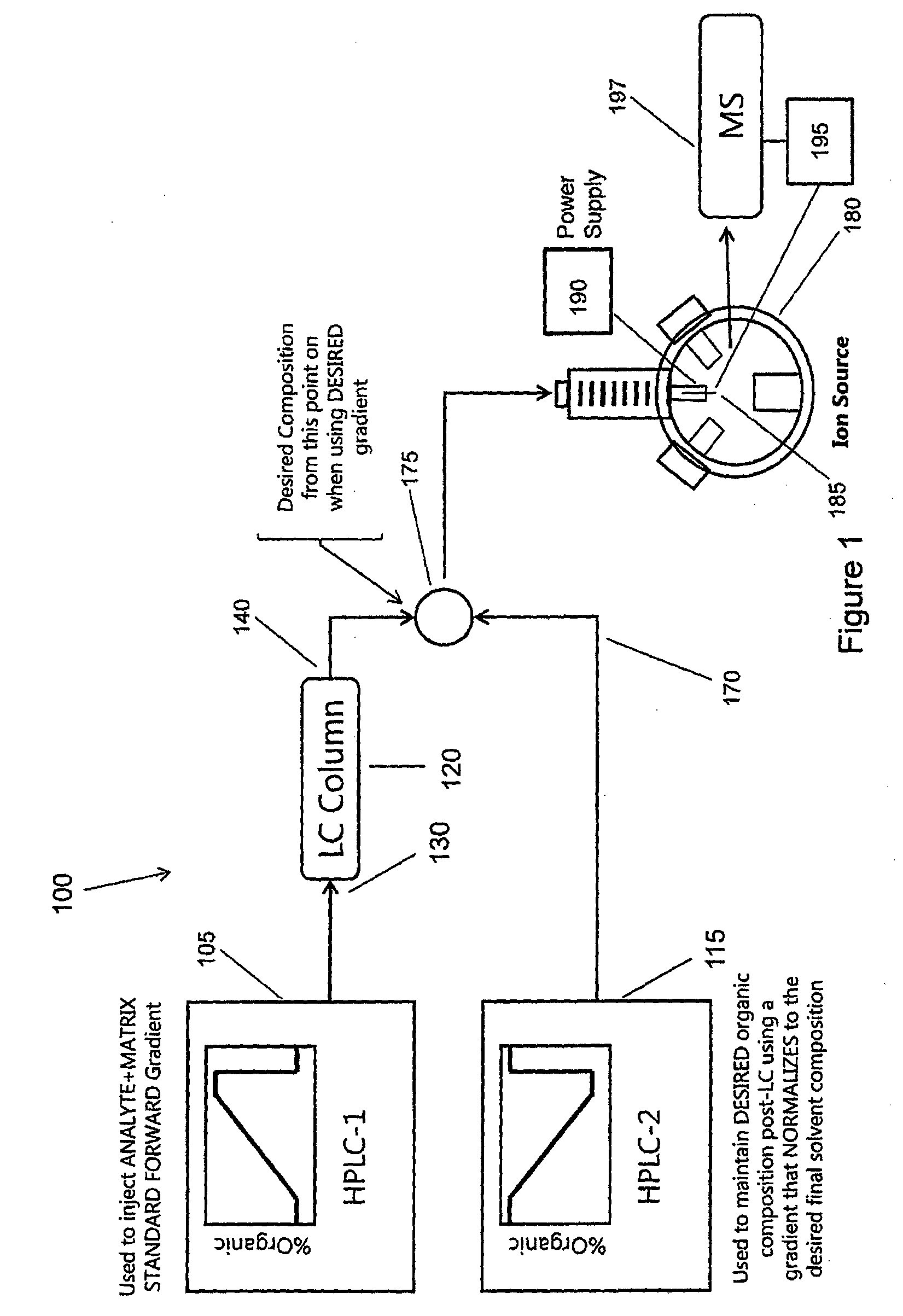
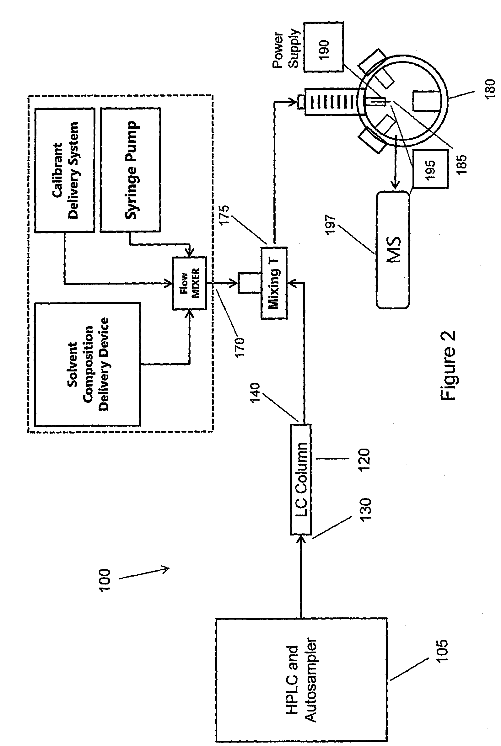
[0151]Differential Ion Mobility—Mass Spectrometry. A differential mobility spectrometer (SelexION™ Technology, AB Sciex, Concord, ON) system as shown in FIGS. 16 and 17 was mounted on a 5500 QTRAP® system (AB Sciex), between a TurboV™ ESI source and the mass spectrometer's sampling orifice. The ESI probe was maintained at a voltage of 4800 V, with a source temperature of 150° C., nebulizing gas...


PUM

PropertyMeasurementUnit
spray currentaaaaaaaaaa
particle sizeaaaaaaaaaa

Abstract

An electrospray ion source method and system is provided for detecting emitter failure comprising a liquid chromatography column suitable for chromatographic separation of a sample. The column can have an inlet for receiving the sample; and an outlet for ejecting the sample. A make-up flow channel is provided for introducing make-up flow of liquid to the sample post-column, wherein the make-up flow normalizes the spray current. An electrospray ionization source is provided having one or more electrospray ionization emitter nozzles for receiving the make-up flow containing sample. A power supply can provide a voltage to the one or more emitter nozzles, and a measurement device can measure and monitor the spray current.

Description

RELATED APPLICATION[0001]This application claims priority to U.S. provisional application No. 61 / 649,037, filed on May 18, 2012, which is incorporated herein by reference in its entirety.FIELD[0002]The applicants' teachings relate to a method and system for introducing make-up flow in an electrospray ion source system, and more specifically for detecting electrospray emitter failure and altering the protonation site of ions.INTRODUCTION[0003]In an electrospray ion source system, oftentimes there can be spontaneous failure of emitters due to the presence of precipitating samples and other fouling agents resulting in spray failure. Detection of spray failure can be problematic since during an LC run, there is a very large spray current range, for example, spanning from 1 nA to 150 nA from the beginning of a gradient to the end of the gradient making monitoring the ion current in this range ineffective. Accordingly, a need exists for reliably detecting electrospray emitter failure.[000...

Claims


Application Information

Patent Timeline
Patent Type & Authority Applications(United States)
IPC IPC(8): H01J49/16G01N27/62H01J49/00H01J49/04
CPCH01J49/165H01J49/0081G01N27/622H01J49/0431
Inventor CAMPBELL, JOHN L.COVEY, THOMASLEBLANC, YVESSCHNEIDER, BRADLEY B.
Owner DH TECH DEVMENT PTE
Why Eureka
Try Eureka