Gas sensor element and gas sensor
- Summary
- Abstract
- Description
- Claims
- Application Information
AI Technical Summary
Benefits of technology
Problems solved by technology
Method used
Image
Examples
example 1
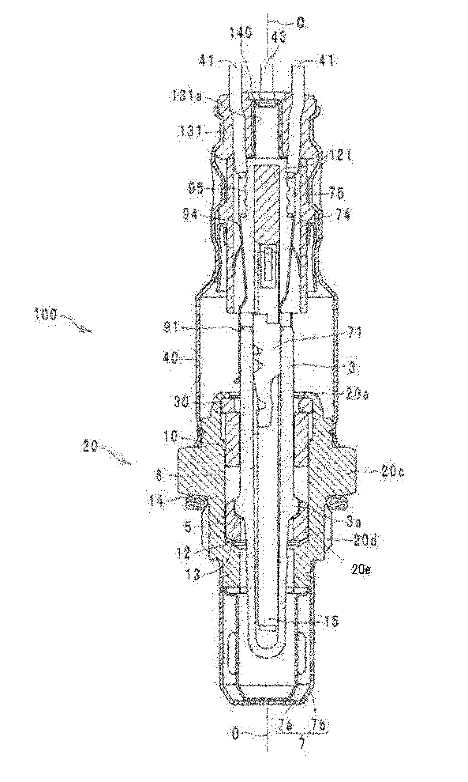
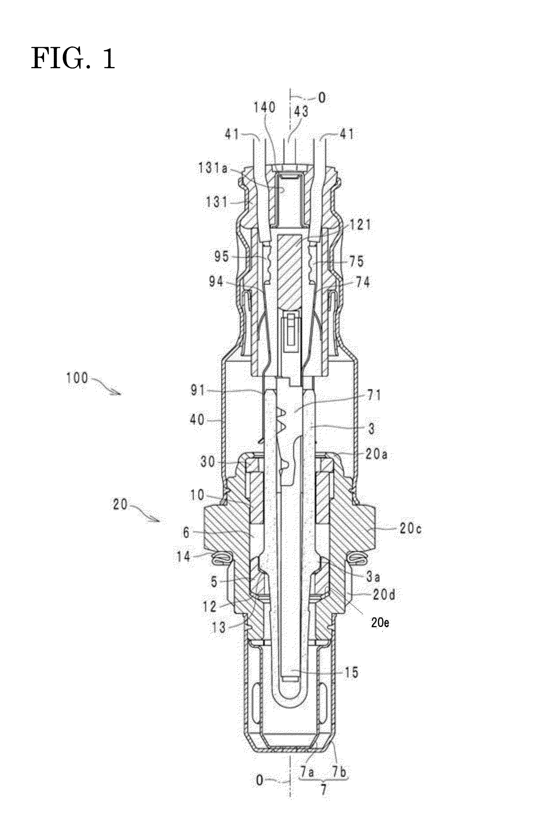
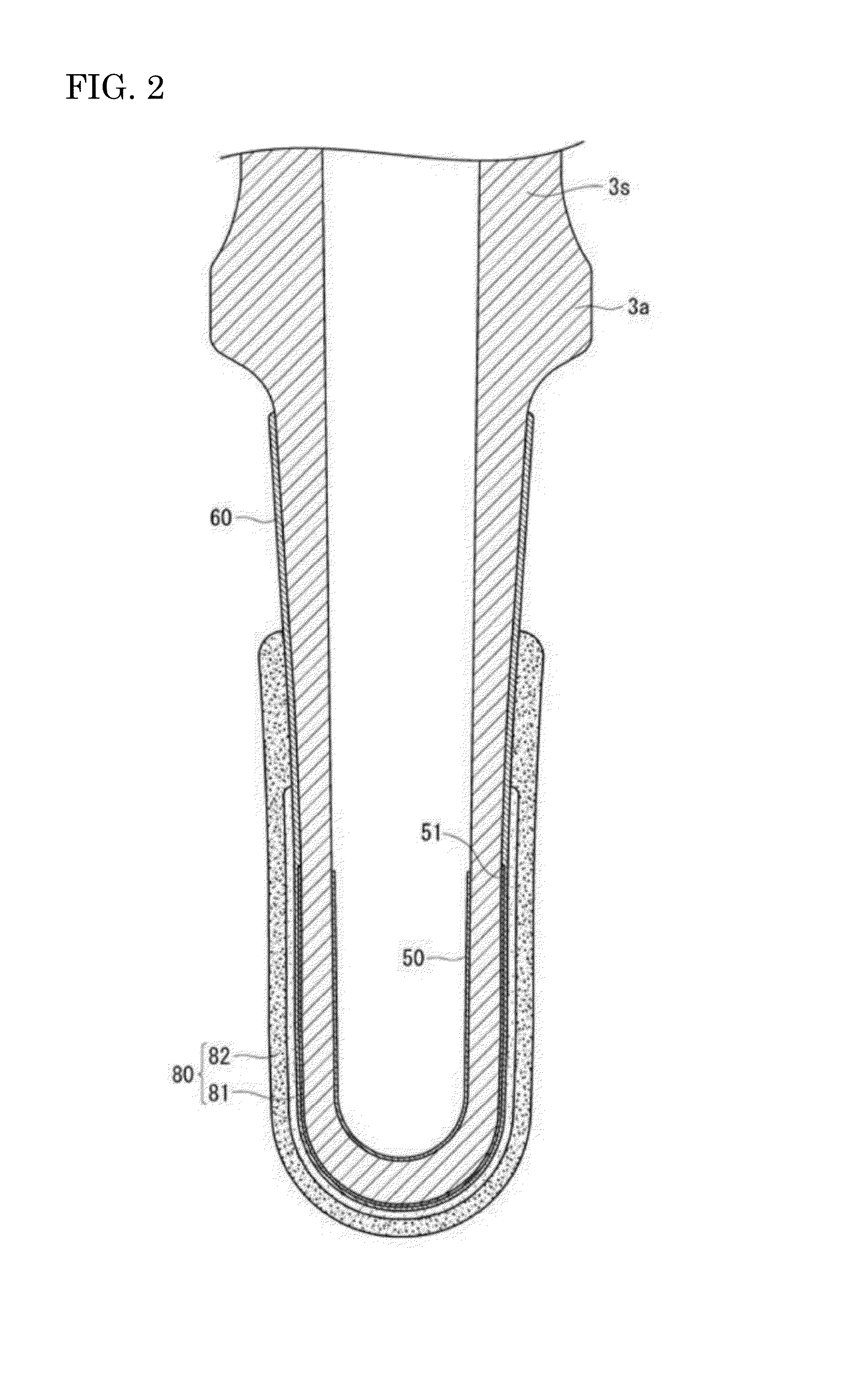
[0083]A solid electrolyte body 3s formed of partially stabilized zirconia, in which 5 mol % of Y2O3 was added to ZrO2, and having a bottomed cylindrical shape as shown in FIGS. 1 and 2 was prepared. Next, an inside electrode 50 made of Pt was formed on an inner circumferential surface of the solid electrolyte body 3s using an electroless plating method. Similarly, an outside electrode 51 made of Pt was formed on the front end side of an outer circumferential surface of the solid electrolyte body 3s using the electroless plating method.
[0084]Next, a ceramic (spinel or the like) sprayed layer 60 was formed (thickness: 150 μm) to cover the outside electrode 51.
[0085]Next, using a dipping method, an inside paste that becomes an inside region 81 was applied (thickness: 250 μm) onto the sprayed layer 60 to cover the outside electrode 51. In the inside paste, only spinel (average particle diameter: 30 μm) was used as ceramic particles, and in this embodiment, glass was not added to the ins...
example 2
[0093]A solid electrolyte body 3s similar to that of Example 1 was prepared, and similarly to Example 1, an inside electrode 50, an outside electrode 51 and a sprayed layer 60 were formed.
[0094]Next, by a dipping method, an inside paste to be an inside region 81 was applied (thickness: 250 μm) onto the sprayed layer 60 to cover the outside electrode 51. In the inside paste, only spinel (average particle diameter: 30 μm) was used as the ceramic particles, and in this embodiment, glass formed of zircon-based glass was further mixed therein at a mixing ratio (mass ratio) of 10 wt % of glass to 100 wt % of ceramic.
[0095]Next, an outside paste to be an outside region 82 was applied (thickness: 450 μm) to a surface of the inside paste, and the entire outside paste was fired at 1000° C. To prepare a slurry for forming the outside paste, spinel (average particle diameter: 30 μm) and titania (average particle diameter: 0.1 μm) were mixed at a mixing ratio of 70 vol % of spinel and 30 vol % o...
example 3
[0099]A solid electrolyte body 3s similar to that of Example 2 was prepared, and similarly to Example 2, an inside electrode 50, an outside electrode 51 and a sprayed layer 60 were formed.
[0100]Next, by a dipping method, an inside paste that becomes an inside region 81 was applied (thickness: 250 μm) onto the sprayed layer 60 to cover the outside electrode 51, and the entire inside paste was fired at 1000° C. In the inside paste, only spinel (average particle diameter: 30 μm) was used as the ceramic particles, and in this embodiment, glass formed of zircon-based glass was further mixed therein at a mixing ratio (mass ratio) shown in Table 3 to 100 wt % of ceramic. In this manner, a gas sensor element was manufactured in which the inside region 81 was formed on a surface of the solid electrolyte body 3s.
[0101]The adhesion evaluation was performed on the gas sensor element thus obtained. A similar evaluation to that of Example 2 was performed as the adhesion evaluation. The results t...
PUM
 Abstract
Description
Claims
Application Information
 - R&D
- Intellectual Property
- Life Sciences
- Materials
- Tech Scout
- Unparalleled Data Quality
- Higher Quality Content
- 60% Fewer Hallucinations
Browse by: Latest US Patents, China's latest patents, Technical Efficacy Thesaurus, Application Domain, Technology Topic, Popular Technical Reports.
© 2025 PatSnap. All rights reserved.Legal|Privacy policy|Modern Slavery Act Transparency Statement|Sitemap|About US| Contact US: help@patsnap.com


