Apparatus for dividing and supplying gas and method for dividing and supplying gas

Active Publication Date: 2015-03-05
FUJIKIN INC +1
View PDF20 Cites 17 Cited by
  • Summary
  • Abstract
  • Description
  • Claims
  • Application Information

AI Technical Summary

Benefits of technology

The present invention provides a gas dividing / supplying apparatus with flow rate control and prevention of transient flow-in. It includes a flow rate control device, multiple divided flow passages with thermal-type mass flow sensors and electrically-operated valves, controllers, and a flow ratio setting calculator. The apparatus is able to control the flow ratio and adjust the opening degrees of the divided flow passages to achieve highly accurate and stable gas supply. It also allows for responsiveness enhancement and cost reduction.

Problems solved by technology

By the way, in the flow rate control devices that are provided to each of the divided flow passages, when gas starts to be supplied, an excessive flow-in of gas (overshooting phenomenon) is liable to easily occur in general, and especially in the thermal-type flow rate control device MFC, the occurrence of the overshooting phenomenon is inevitable.
In the thermal-type flow rate control device and a thermal-type mass flow sensor, variation of the zero point due to temperature and change in a detected flow rate caused by pressure in a flow regulating layer portion are relatively large and enhancement of flow rate control accuracy is hindered a lot.
Further, in case a gas flow rate for dividing and supplying is switched frequently, it is difficult to increase responsiveness of the divided flow rate control as it takes quite long time from when the divided flow rate control procedure including setting of a flow ratio (divided flow ratio) is started to when a stable control is established.
Here, the occurrence of overshooting of gas in the gas dividing and supplying system inevitably causes a decrease in operating efficiency of semiconductor manufacturing facilities etc. or a decrease in quality of products.
This significantly decreases accuracy in control of gas of the divided flow rate Q1.
However, there are still many issues need to be solved left in the gas dividing / supplying apparatus of FIG. 16.
For example, a pulse electrically-operated cam drive type valve is often used as the electrically-operated valve 7 as the valve is capable of control relatively large flow, however, in the pulse motor-operated cam drive type valve, a position of the valve element in fully-closed state is regulated with a spring mechanism with applying a fixed pressing load to a valve sheet, and therefore miniaturization and simplification of the electrically-operated valve 7 is not easily attainable due to the spring mechanism and positioning of the valve element in fully-closed state itself is troublesome.
Additionally, sheet-leaking often occurs when the valve is fully-closed.
Therefore, there are issues of decrease in accuracy of opening degree control and divided flow rate control.
As a result, under reduced-pressure environment, such as 100 Torr or under, an issue of decreased divided flow rate control accuracy of each of the divided flow passages L1 to Ln is caused by the difference among the pressures in the flow rate regulating layers of the thermal-type mass flow sensors.
Furthermore, PID control parameters for the switching-type controllers 16a to 16d, which are main parts of the divided flow rate control devices, are all set as fixed values and the divided flow rate controls are conducted by the fixed PID control parameters whether the total flow rate Q is high or low, and as a result, control responsiveness and control accuracy are not enhanced because the PID control parameters are not the most suitable for controlling.
Therefore, the controls of the opening degree interfere mutually and the controls easily become unstable, and as a result, it takes longer time for the controls to be stabilized.
This lowers responsiveness of the divided flow rate control and the control responsiveness may not be enhanced.

Method used


Image

  • Apparatus for dividing and supplying gas and method for dividing and supplying gas
  • Apparatus for dividing and supplying gas and method for dividing and supplying gas
  • Apparatus for dividing and supplying gas and method for dividing and supplying gas

Examples


Embodiment Construction

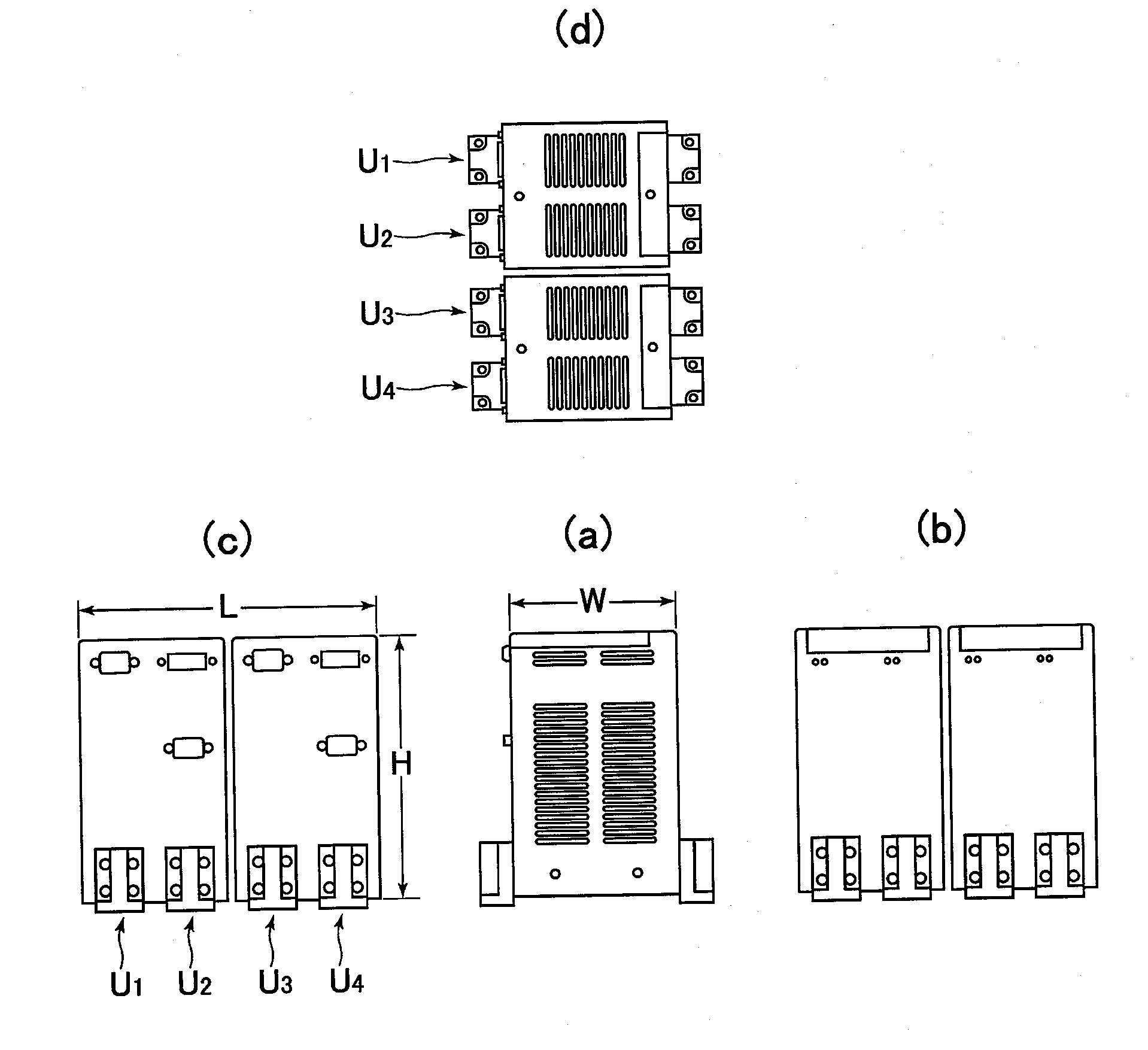
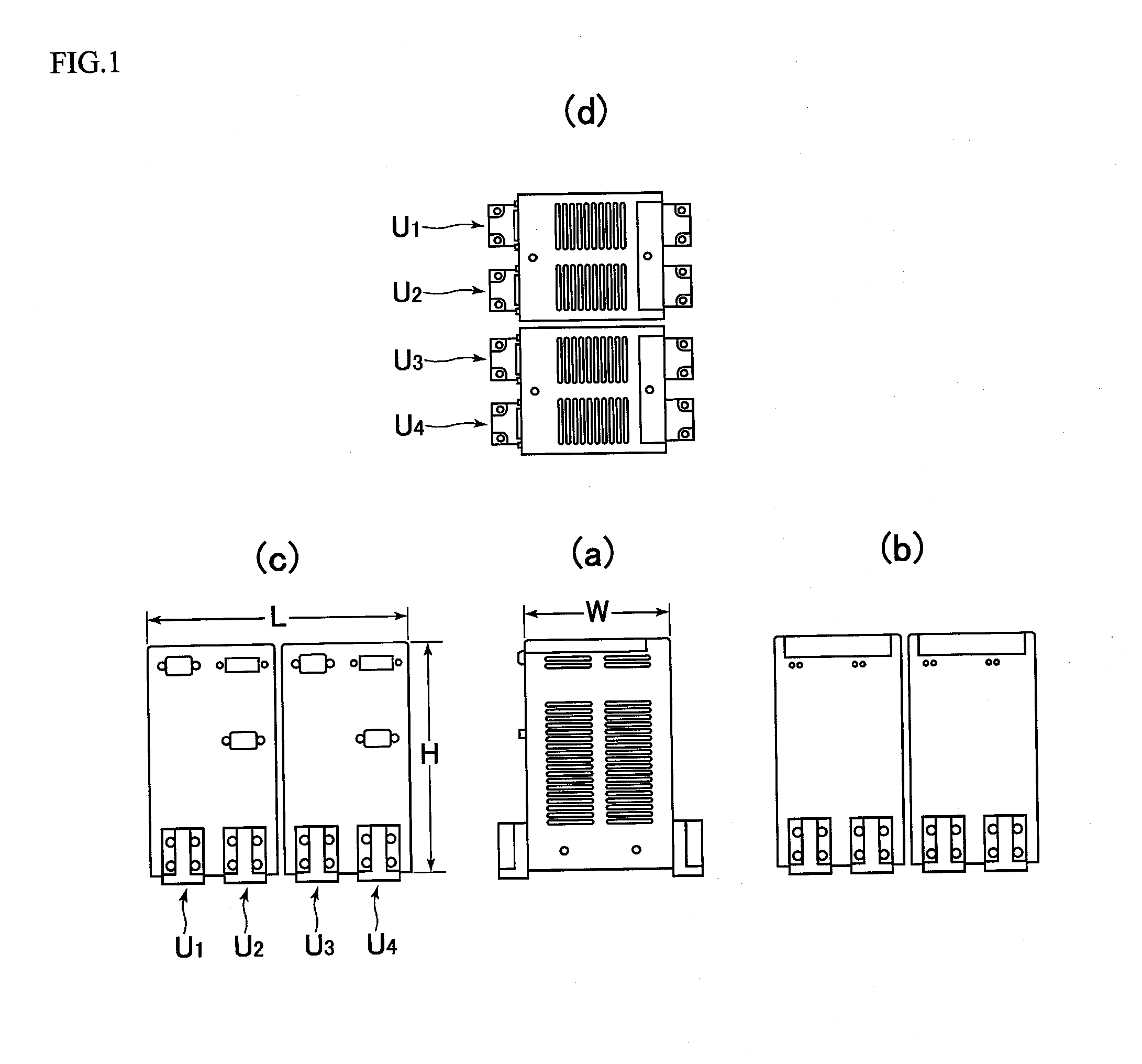
[0072]Hereinafter, an embodiment of the present invention will be described with reference to drawings. FIG. 1 is an external view of a divided flow rate controlling portion of a gas dividing / supplying apparatus with four divided flow passages according to an embodiment of the present invention and (a) is a front view, (b) is a right-side view, (c) is a left-side view and (d) is a plan view. In the embodiment, four divided flow rate controlling portions U1 to U4 are configured to supply gas G, which is divided based on predetermined divided flow rates Q1 to Q4, to four locations where the gas is used through divided flow passages L1 to L4 of four systems (n=4) respectively, by being combined integrally in parallel (arranged side by side).

[0073]On the other hand, external dimensions of the gas dividing / supplying apparatus with four divided flow passages are approximately 160 mm (height), 100 mm (width) and 180 mm (length), and the portion U1 together with the portion U2 and the porti...


PUM


Abstract

An apparatus for dividing and supplying gas is provided with a flow rate control device, a plurality of divided flow passages of gas flowing from the flow rate control device, thermal-type mass flow sensors disposed to the divided flow passages, electrically-operated valves disposed on a downstream side of the thermal-type mass flow sensors, controllers that control the electrically-operated valves, and a flow ratio setting calculator that calculates a total flow rate, then calculates flow rates of the divided flow passages, and then inputs the calculated flow rates as set flow rates to each controllers. One of the divided flow passages with the highest set flow rate is put in an uncontrolled state, and opening degree for each of the rest divided flow passages is controlled, and then feedback control of the divided flow rate of each of the divided flow passages is implemented by each of the controllers.

Description

CROSS-REFERENCE TO RELATED APPLICATIONS[0001]This application claims priority to Japanese Patent Application No. 2013-179237 filed on Aug. 30, 2013, the entire contents of which are incorporated by reference herein.TECHNICAL FIELD[0002]The present invention relates to an improvement in a gas dividing and supplying system that divides and supplies gas emitted from a gas supply source based on a predetermined flow ratio to a plurality of divided gas flow passages each of which is provided with a thermal-type mass flow sensor and connected each other in parallel. More particularly, relates to an apparatus for dividing and supplying gas and a method for dividing and supplying gas that achieve simplification and miniaturization of a structure of the apparatus for dividing and supplying gas and is capable of easily and reliably preventing the occurrence of an excessive flow-in of gas (i.e., overshooting) at the beginning of supplying gas to each of the divided flow passages as well as enh...

Claims


Application Information

Patent Timeline
IPC IPC(8): G05D7/06G05D11/16
CPCG05D11/16G05D7/0641G05D7/0664Y10T137/0363Y10T137/2529Y10T137/2562Y10T137/7759Y10T137/7761H01L21/02G05D11/132
Inventor TAKAHASHI, EIJISASAKI, NORIKAZUSAWACHI, ATSUSHISAWADA, YOHEIIKEDA, NOBUKAZUDOHI, RYOUSUKENISHINO, KOUJI
Owner FUJIKIN INC
Why Eureka
Try Eureka