Vacuum cleaner
a vacuum cleaner and vacuum cleaner technology, applied in vacuum cleaners, cleaning equipment, domestic applications, etc., can solve the problems of inconvenience for users, and achieve the effect of smooth chang
- Summary
- Abstract
- Description
- Claims
- Application Information
AI Technical Summary
Benefits of technology
Problems solved by technology
Method used
Image
Examples
first embodiment
[0066]Hereinafter, a vacuum cleaner according to the present disclosure will be described in detail with reference to the accompanying drawings.
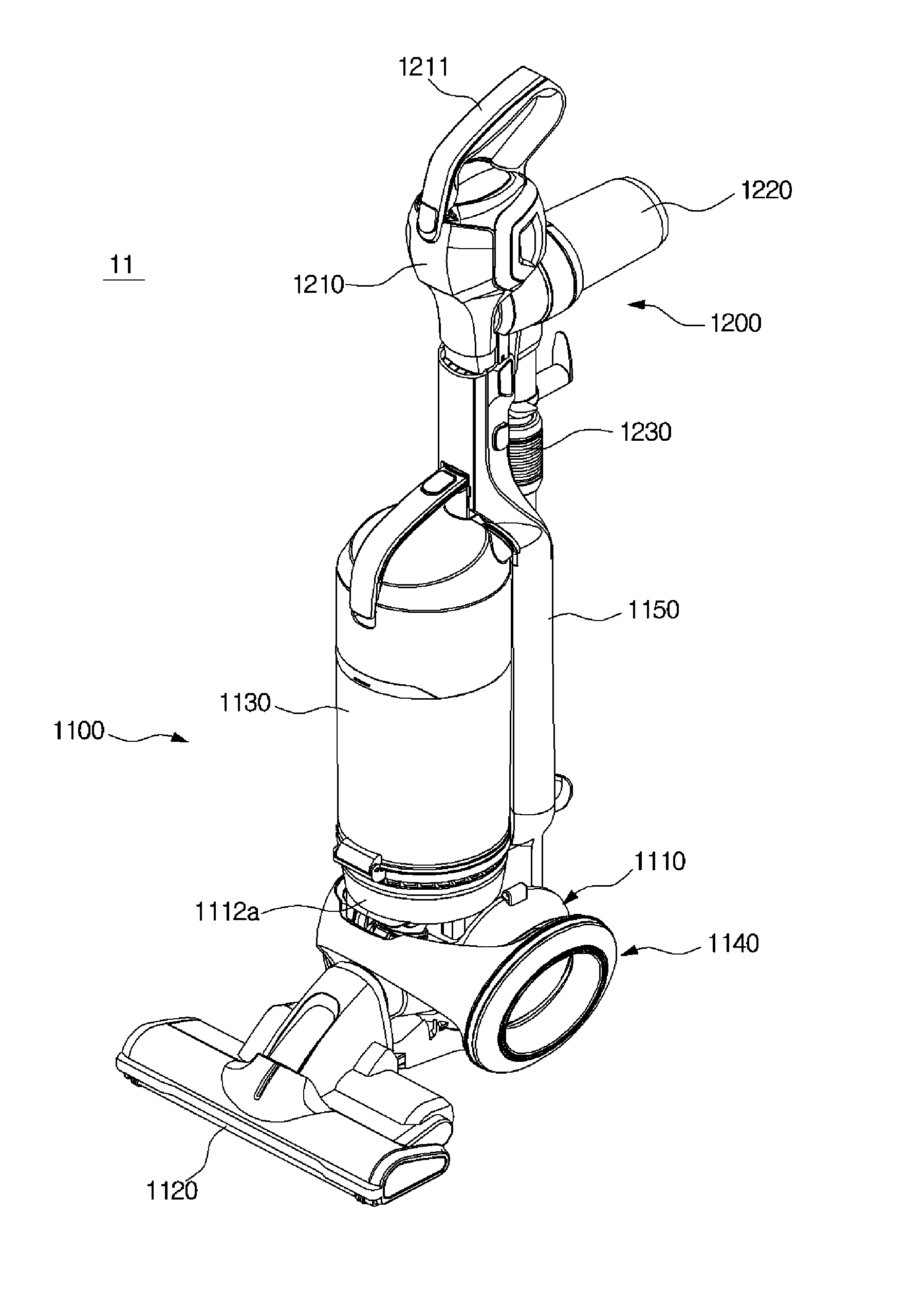
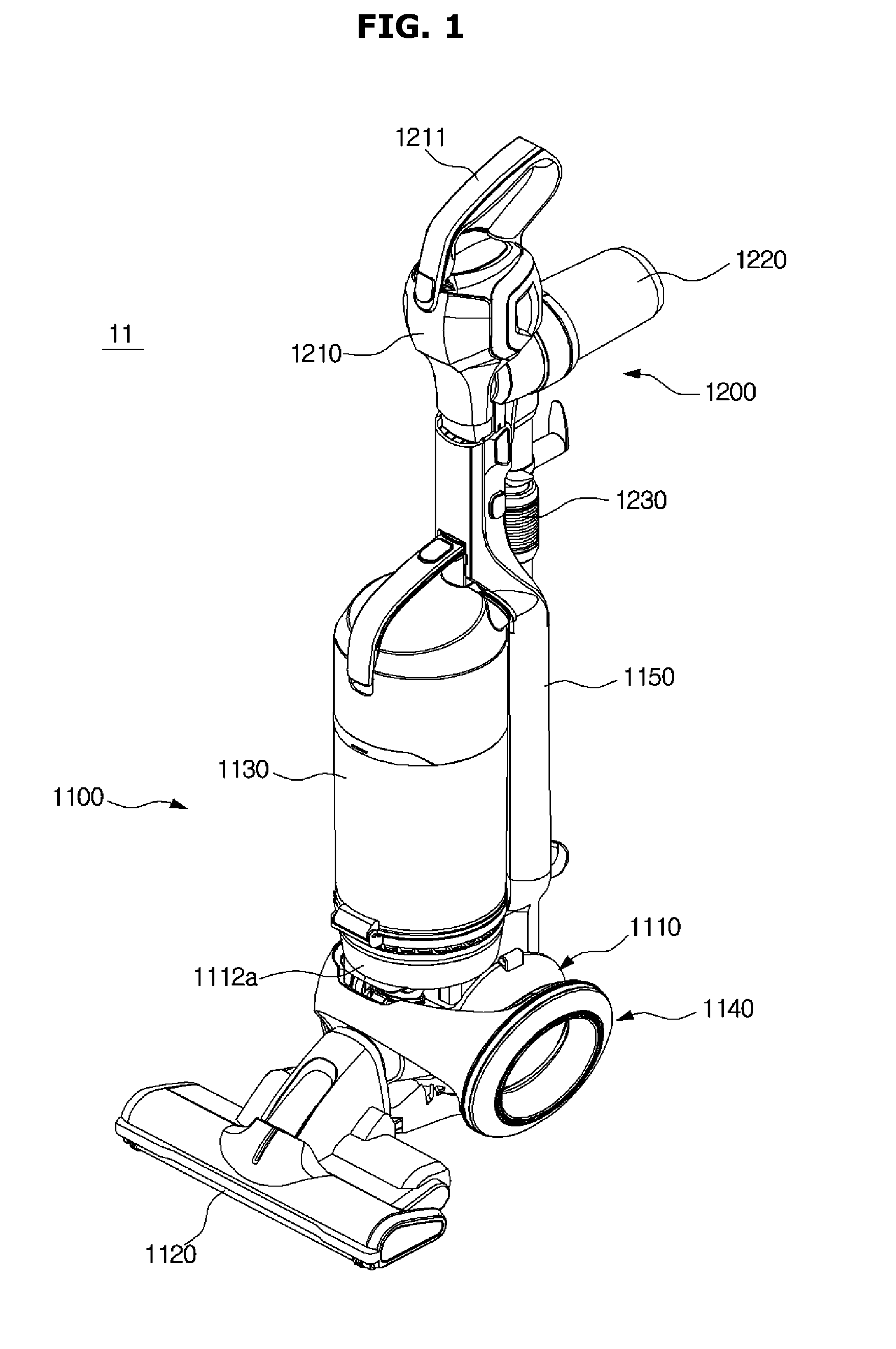
[0067]As illustrated in FIG. 1, a vacuum cleaner 11 according to a first embodiment of the present disclosure includes an upright cleaner module 1100 enabling a user to clean a floor in an upright mode, and a handy cleaner module 1200 that is removably installed on the upright cleaner module 1100 and enables the user to do cleaning in a handy mode after being decoupled from the upright cleaner module 1100.
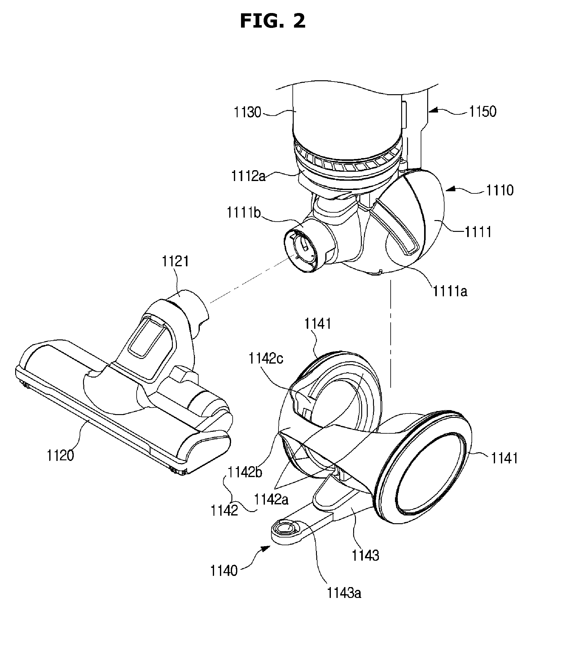
[0068]The upright cleaner module 1100 includes an upright main body 1110 in which an upright fan motor 1170 (see FIG. 8) generating a suction force when cleaning is done in the upright mode is housed, a head unit 1120 that is connected to a front side of the upright main body 1110, comes into contact with a floor to be cleaned, and suctions dust on the floor along with air, an upright dust collection unit 1130 that is mounted on an upper si...
second embodiment
[0105]That is, the present disclosure as illustrated in FIGS. 13 and 14 can obtain an effect of reducing the rotational radius of the vacuum cleaner without configurations corresponding to the guide rails 1111a and the guides 1142c.
[0106]In detail, as illustrated in the figures, when the user rotates the extension frame 1150 to the left or right side with the extension frame 1150 inclined toward a rear upper side, the extension frame 1150 and the head unit 1120 form an angle due to the leftward / rightward rotation of the extension frame 1150. Thereby, the rotational radius of the vacuum cleaner is reduced. In this case, the head unit 1120 is preferably fixedly installed at the front side of the wheel assembly 1140.
third embodiment
[0107]Hereinafter, a vacuum cleaner according to the present disclosure will be described in detail with reference to the drawings.
[0108]As illustrated in FIGS. 15 and 16, a vacuum cleaner 21 according to a third embodiment of the present disclosure includes an upright cleaner module 2100 enabling a user to clean a floor, a pipe module 2200 that is removably installed on the upright cleaner module 2100 and enables the user to clean various places which the upright cleaner module 2100 cannot clean after being decoupled from the upright cleaner module 2100, and a connecting hose 2300 that connects the upright cleaner module 2100 and the pipe module 2200 and causes a suction force generated from the upright cleaner module 2100 to be transmitted to the pipe module 2200.
[0109]The upright cleaner module 2100 includes an upright main body 2110 in which a fan motor (not shown) generating a suction force when a floor is cleaned is housed, a head unit 2120 that is connected to a front side of...
PUM
 Abstract
Description
Claims
Application Information
 - R&D
- Intellectual Property
- Life Sciences
- Materials
- Tech Scout
- Unparalleled Data Quality
- Higher Quality Content
- 60% Fewer Hallucinations
Browse by: Latest US Patents, China's latest patents, Technical Efficacy Thesaurus, Application Domain, Technology Topic, Popular Technical Reports.
© 2025 PatSnap. All rights reserved.Legal|Privacy policy|Modern Slavery Act Transparency Statement|Sitemap|About US| Contact US: help@patsnap.com


