
Power controller

Active Publication Date: 2015-02-26
MICROPAC IND
View PDF6 Cites 30 Cited by
  • Summary
  • Abstract
  • Description
  • Claims
  • Application Information

AI Technical Summary

Benefits of technology

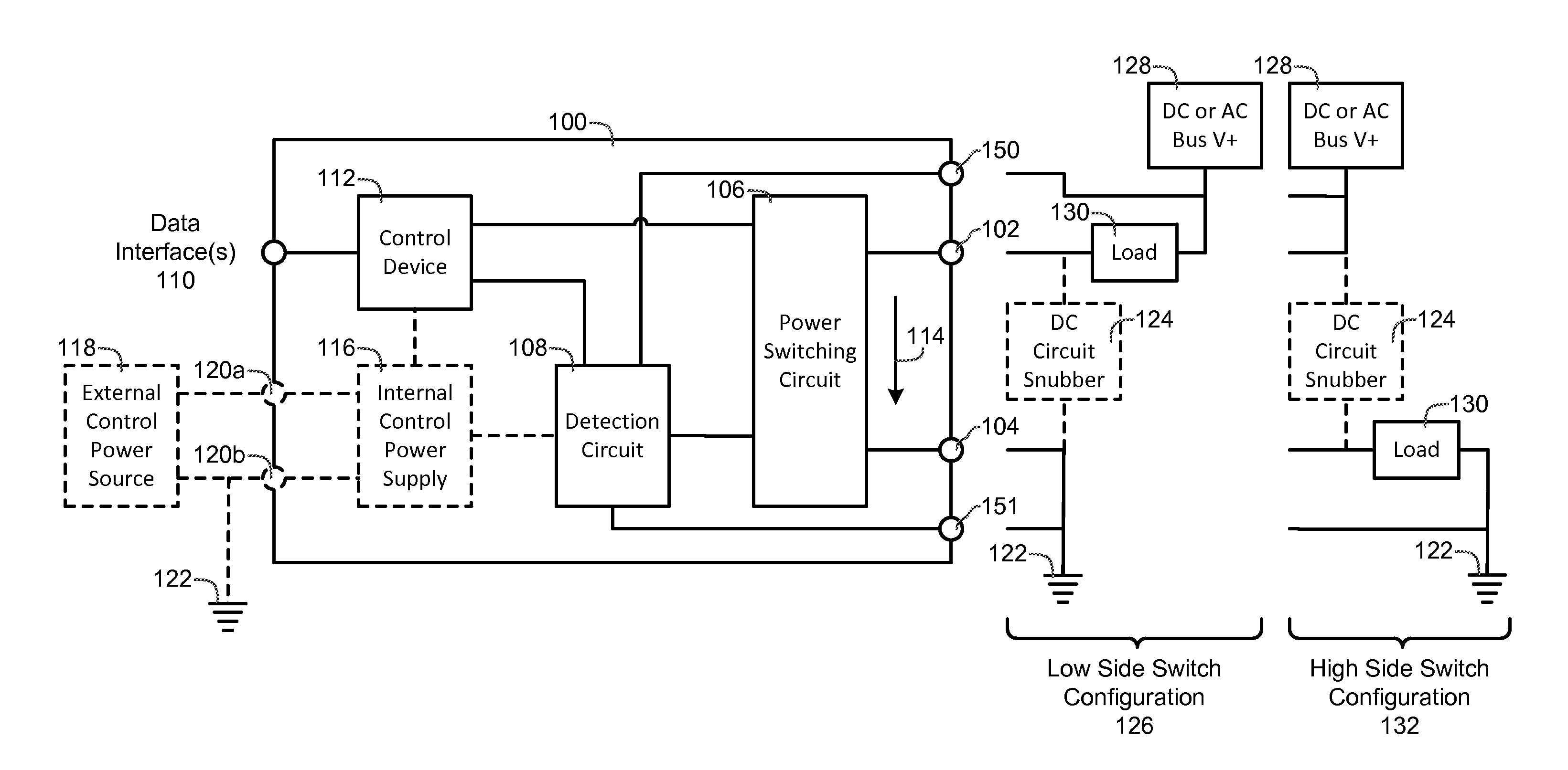
The present invention introduces new features to a Solid State Relay (SSR) to prevent failures and improve reliability. These features include remote load current monitoring, remote operation, and over-current or over-voltage fault detection with near-instant OFF control. These features work together to create an Industrial Power Controller (IPC) that can better control power distribution and prevent malfunctions.

Problems solved by technology

Relays and controllers that use optical coupling for setting the ON or OFF condition and use power FET devices for switching AC or DC loads have been known to have some vulnerabilities with catastrophic load failure.
These load failures can often cause destructive damage of relays and controllers, including burning or melting of enclosures, and / or failure of the load switching FETs.

Method used


Image

  • Power controller
  • Power controller
  • Power controller

Examples


Embodiment Construction

[0025]While the making and using of various embodiments of the present invention are discussed in detail below, it should be appreciated that the present invention provides many applicable inventive concepts that can be embodied in a wide variety of specific contexts. The specific embodiments discussed herein are merely illustrative of specific ways to make and use the invention and do not delimit the scope of the invention. For example, the present invention is described with respect to gene sequence data. The present invention, however, is not limited to gene sequence data or the specific design examples described herein.

[0026]To facilitate the understanding of this invention, a number of terms are defined below. Terms defined herein have meanings as commonly understood by a person of ordinary skill in the areas relevant to the present invention. The terminology herein is used to describe specific embodiments of the invention, but their usage does not delimit the invention, except...


PUM


Abstract

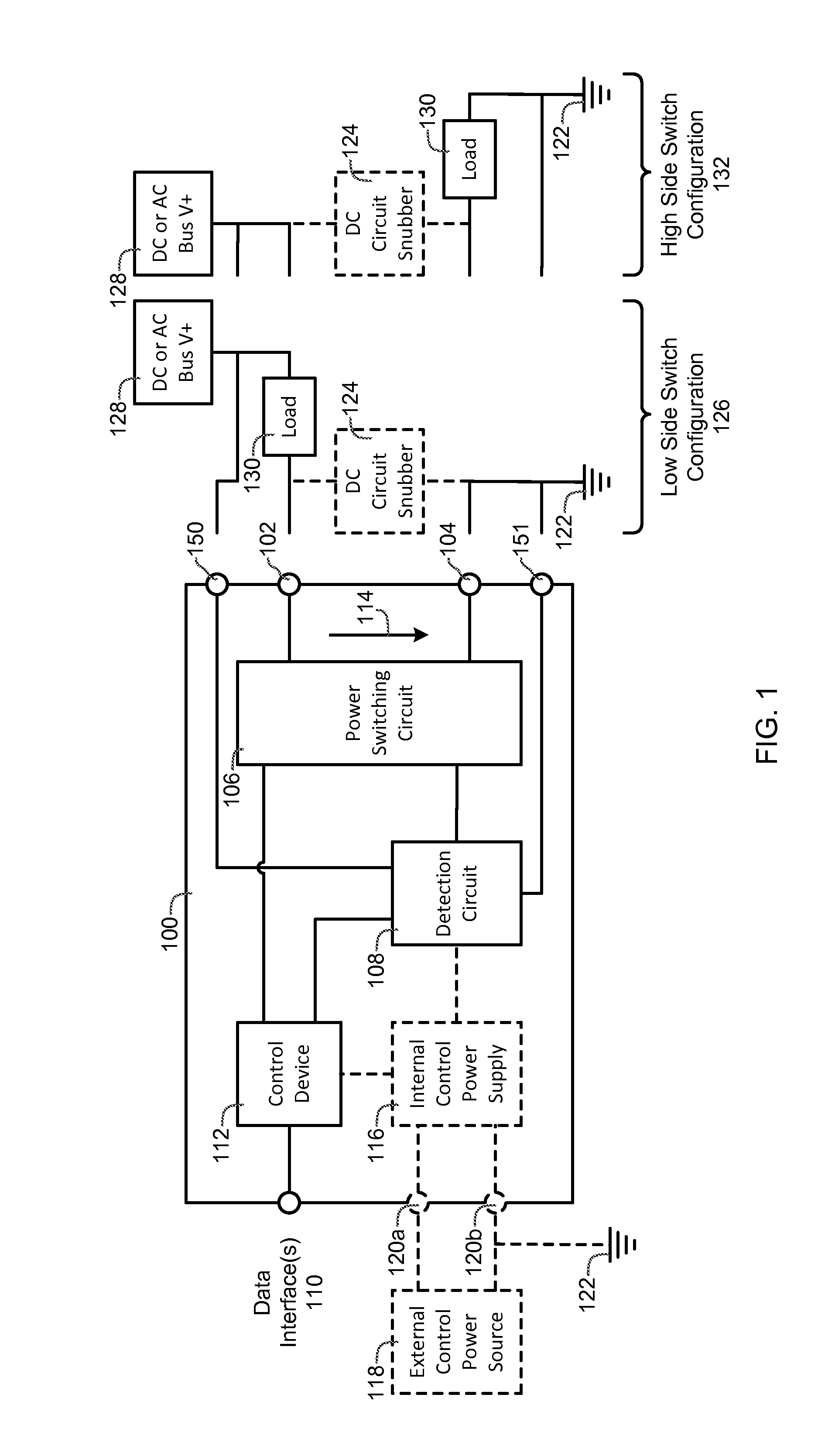
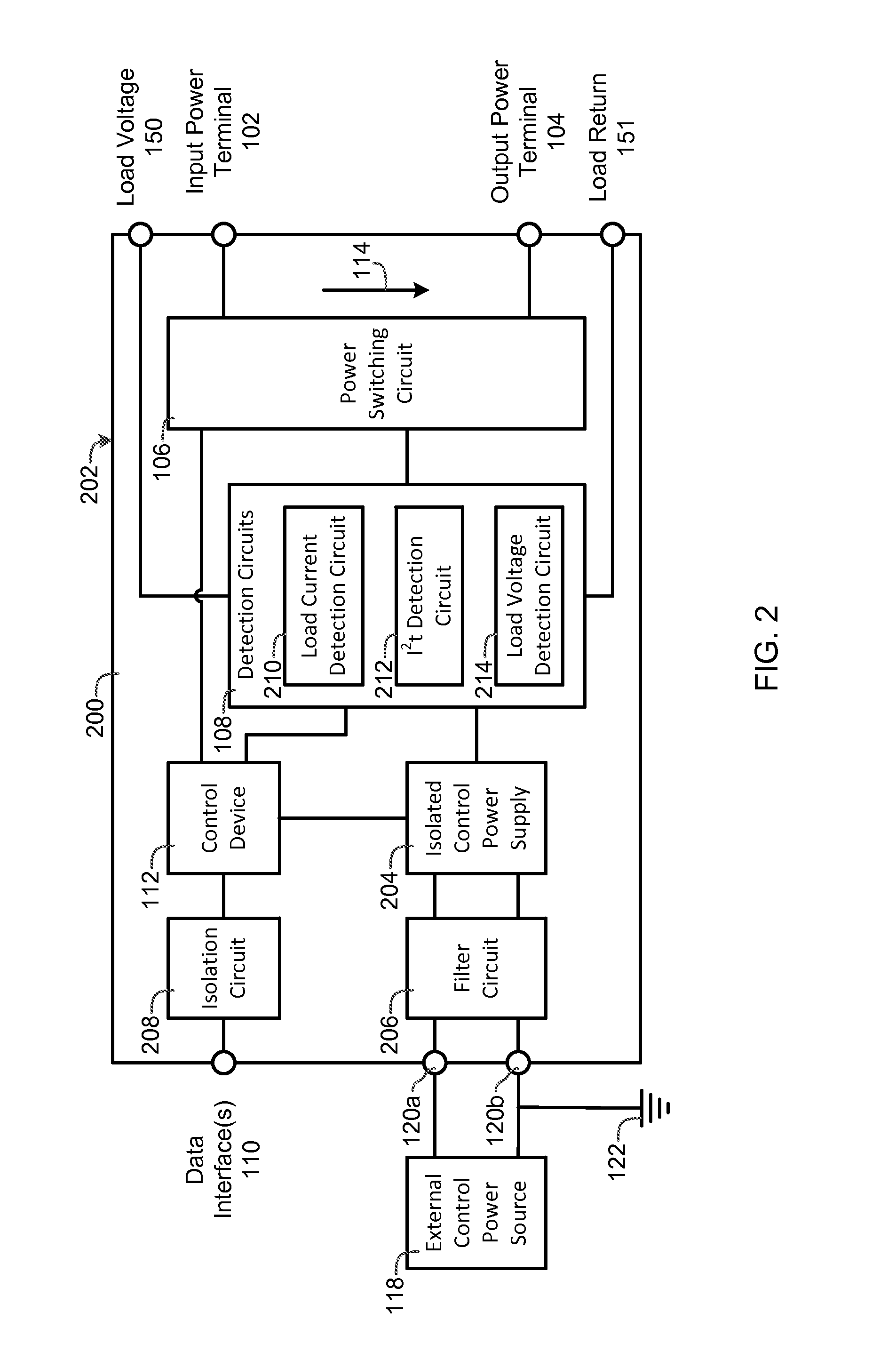
A power controller includes an input power terminal, an output power terminal, a power switching circuit connected between the input power terminal and the output power terminal, a detection circuit connected to the power switching circuit, one or more data interfaces, and a control device connected to the detection circuit and the one or more data interfaces. The detection circuit measures a load current and a current squared time (I2t) value between the input power terminal and the output power terminal. The control device automatically turns the power switching circuit “OFF” whenever the load current exceeds a first value or the current squared time value exceeds a second value or an “OFF” signal is received from the one or more data interfaces, and automatically turns the power switching circuit “ON” whenever an “ON” signal is received from the one or more data interfaces.

Description

PRIORITY CLAIM AND RELATED APPLICATION DATA[0001]This application is a non-provisional application of U.S. provisional patent application No. 61 / 870,117, filed on Aug. 26, 2013 which application is hereby incorporated by reference in its entirety.STATEMENT OF FEDERALLY FUNDED RESEARCH[0002]Not Applicable.TECHNICAL FIELD OF THE INVENTION[0003]The present invention relates in general to the field of power controllers.BACKGROUND OF THE INVENTION[0004]Without limiting the scope of the invention, its background is described in connection with Solid State Relays (SSR) and Industrial Power Controllers (IPC). Relays and controllers that use optical coupling for setting the ON or OFF condition and use power FET devices for switching AC or DC loads have been known to have some vulnerabilities with catastrophic load failure. These load failures can often cause destructive damage of relays and controllers, including burning or melting of enclosures, and / or failure of the load switching FETs. Co...

Claims


Application Information

Patent Timeline
IPC IPC(8): G05F1/66G01R21/06
CPCG01R21/06G05F1/66H03K17/0822H03K17/18H03K17/691H03K2217/0027H02H3/08H03K17/61H03K17/785H03K2217/0081H03K17/7955
Inventor BALDRIDGE, WAYNE
Owner MICROPAC IND
Learn More