Image forming device

a technology of forming device and image, which is applied in the field of image forming device, can solve the problems of inability to apply, inability to confirm the form of the final printed matter, and inability to understand the manner in which image data would be combined after combination processing, etc., and achieves the effect of easy inspection, easy inspection, and easy combining of images

Inactive Publication Date: 2015-02-26
SHARP KK
View PDF5 Cites 2 Cited by
  • Summary
  • Abstract
  • Description
  • Claims
  • Application Information

AI Technical Summary

Benefits of technology

[0010]Accordingly, in order to provide the image forming device with a higher level of operability, it is desirable that it be also applicable to single-sided printing, and that changes in layout are able to be confirmed easily on a preview screen.
[0011]Preferred embodiments of the present invention provide an image forming device with which a layout for printing is easily changed by intuitive operations, regardless of whether printing is single-sided or double-sided, and a printing image after changes is easily confirmed before printing.

Problems solved by technology

There have been problems, however, in that working with a setup screen has not made it easy to edit the image data to be printed and has also made it difficult to understand the manner in which the image data would be combined after combination processing has been executed.
However, the technology of Japanese Patent Application Laid-Open Publication No. 2006-247873 has a problem that it cannot be applied except when specifying spread / non-spread for bookmaking of printed matter that is printed on both sides.
Furthermore, in the image forming device of Japanese Patent Application Laid-Open Publication No. 2006-247873, the order of the individual pages that constitute the printed data after specification cannot be changed on-screen, and the specifications of spread pages / non-spread pages are not displayed, either.
Therefore, there is also a problem in that the form of the final printed matter cannot be confirmed without actually printing it.

Method used


Image

  • Image forming device
  • Image forming device
  • Image forming device

Examples


first preferred embodiment

[0040]In the following description and drawings, the same reference numbers and names are assigned to the same components. The functions thereof are also the same. Therefore, the detailed description of these components will not be repeated.

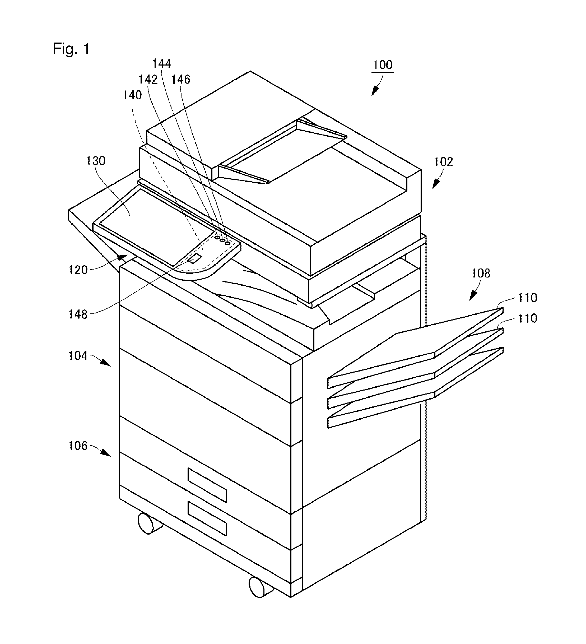
[0041]With reference to FIG. 1, an image forming device 100 according to a preferred embodiment of the present invention preferably is a multifunction printer (MFP) equipped with scanner functions, copy functions, facsimile (hereinafter noted as “fax”) functions, and so forth. As a result of a user setting one of operating modes such as scanner mode, copy mode, and fax mode, the image forming device 100 executes processing which corresponds to the operating mode that has been set. It is assumed that the document read in the present preferred embodiment is configured of a plurality of pages.

[0042]With reference to FIGS. 1 and 3, the image forming device 100 includes an operating unit 120. As shown in FIG. 1, the operating unit 120 is a plate-shape...

second preferred embodiment

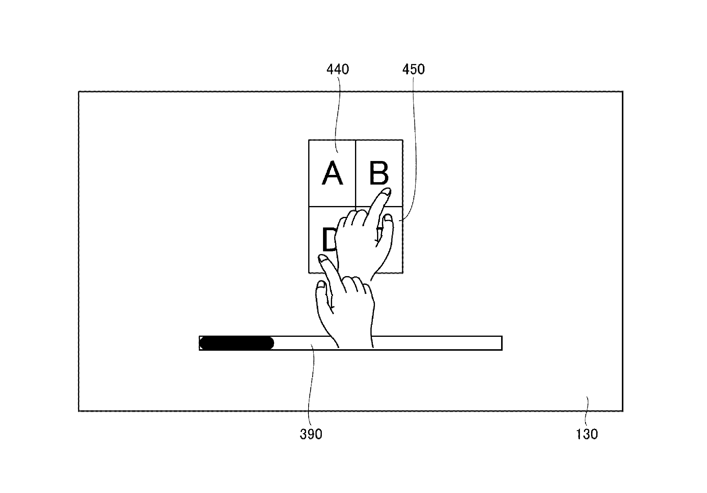
[0092]In the preferred embodiment described above, a case was described in which 4-in-1 combination processing preferably is executed by touching preview images. In a second preferred embodiment of the present invention, division processing preferably is additionally executed by touching a preview image in cases where a previously combined image is to be divided into a plurality of images as well. Apart from this point, the image forming device according to the second preferred embodiment operates in the same way as the image forming device according to the first preferred embodiment. Because of this, explanations are not repeated below.

[0093]It is assumed that the image 440, which has undergone 2-in-1 processing, is displayed in the touch panel display 130 along with the image 420 and the image 430 as shown in FIG. 9. The document size of each of these displayed images is A4. The operation of the image forming device 100 which is executed when the image 440 among these images is di...

third preferred embodiment

[0100]In the aforementioned first and second preferred embodiments, the cases of combining or dividing images were described. In the image forming device according to a third preferred embodiment of the present invention, images can not only be combined or divided, but the image display order can also be changed. Apart from this point, the image forming device according to the third preferred embodiment operates preferably in the same or substantially the same way as the image forming device according to the first or second preferred embodiment. For this reason, explanations of elements and operations duplicative of the first or second preferred embodiment will not be repeated below.

[0101]The operation of the image forming device 100 when touch input to change the display order of the images 400 through 430 lined up in the order shown in FIG. 6 is detected will be described with reference to FIGS. 3 through 6, 16, and 17.

[0102]With reference to FIG. 16, when touch input is detected ...


PUM


Abstract

An image forming device enables a printing layout to be changed by intuitive operations and a printing image to be confirmed easily before printing, regardless of whether printing is single-sided or double-sided. A plurality of images that are of the same size as each other are displayed on a touch panel so as to be separated from each other. If two touch inputs simultaneously performed on first and second images are detected, and the distance between the first and second images that have been moved accompanying the movement of the individual touch positions respectively indicated by the two touch inputs has become equal to or less than a specified distance, then the image forming device generates a third image in which the first and second images are arranged adjacently. Furthermore, the image forming device displays the third image on the touch panel instead of the first and second images. The user combines the two images intuitively and easily. Because the images that have been combined are displayed on the touch panel, it is possible to easily check how the two images are to be combined and printed.

Description

BACKGROUND OF THE INVENTION[0001]1. Field of the Invention[0002]The present invention relates to an image forming device and particularly to an image forming device with which image data is capable of being edited.[0003]2. Description of the Related Art[0004]One of the functions of an image forming device is the so-called combine function, which sets up a multiple-page document so as to be printed on a single sheet of paper. Functions that set up a document with N number of pages so as to be printed on a single sheet of paper may be referred to as “N-in-1 functions” below.[0005]In conventional image forming devices, once document reading is complete, an N-in-1 function key is displayed on the display screen. The user can set whether to enable or disable the N-in-1 function, the joining pattern for the documents to be combined, and the like, by working with the setup screen (not shown) that is displayed when the N-in-1 function key is pressed. There have been problems, however, in th...

Claims


Application Information

Patent Timeline
Patent Type & Authority Applications(United States)
IPC IPC(8): H04N1/387H04N1/393H04N1/00
CPCH04N1/3876H04N1/00392H04N1/00411H04N2201/325H04N1/393H04N2201/0094H04N1/00456H04N1/387H04N1/00381H04N1/00461
Inventor ONISHI, TAKAHISA
Owner SHARP KK
Why Eureka
Try Eureka