
Sensor for contactless electrocardiographic measurement

a contactless electrocardiographic and sensor technology, applied in the direction of instruments, diagnostic recording/measuring, positive displacement liquid engines, etc., can solve the problems of poor or even unusable signal, difficult to ensure a sufficiently good electric contact between the electrode and the skin, and relatively difficult to ensure a sufficiently high contact pressure and a sufficiently large contact area between the measurement area of the electrod

Active Publication Date: 2015-02-26
FORD GLOBAL TECH LLC
View PDF8 Cites 8 Cited by
  • Summary
  • Abstract
  • Description
  • Claims
  • Application Information

AI Technical Summary

Benefits of technology

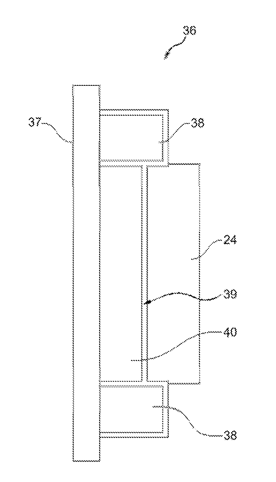
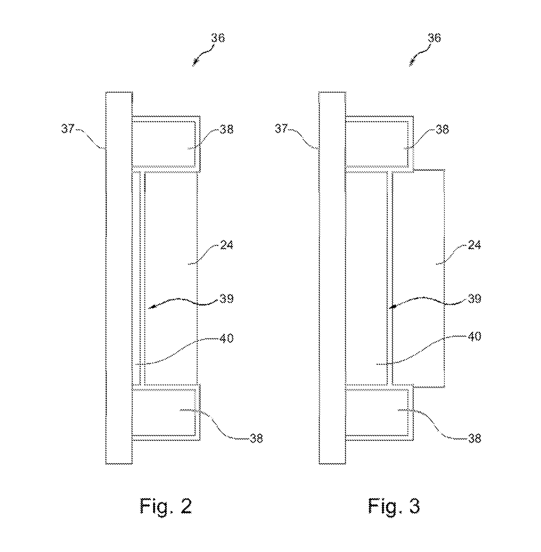
The present invention relates to a sensor and a sensor array for contactless electrocardiographic measurement on people, in vehicle applications. The sensor provides a reliable signal with high quality and allows for reliable evaluations of bodily functions and vital parameters of the person. The sensor includes a mechanism for adjusting the distance between the electrode and the person being examined, which increases the contact pressure and area, resulting in a better measurement signal. The sensor can be adapted to the form of the body part in contact with the electrode, and its flexible electrode material allows for a more precise modification of the electrode form dependent on the pressure present in the bellows. A sensor array comprises multiple sensors and can be targeted to increase the contact pressure or area with the person being examined.

Problems solved by technology

However, it is found often to be difficult to ensure a sufficiently good electric contact between the electrode and the skin, and hence the body of the person to be examined.
In general, those electrodes which have a large distance, e.g. to the back of the person to be examined, lead to a poor or even unusable signal.
However, in the case of relatively slim persons—due to their low weight—or in the case of persons which have an anatomical deformation such as e.g. lumbar hyperlordosis, it will be relatively difficult to ensure a sufficiently high contact pressure and a sufficiently large contact area between the measurement area of the electrode and the person to be examined.

Method used


Image

  • Sensor for contactless electrocardiographic measurement
  • Sensor for contactless electrocardiographic measurement
  • Sensor for contactless electrocardiographic measurement

Examples


Embodiment Construction

[0031]As required, detailed embodiments of the present invention are disclosed herein; however, it is to be understood that the disclosed embodiments are merely exemplary of the invention that may be embodied in various and alternative forms. The figures are not necessarily to scale; some features may be exaggerated or minimized to show details of particular components. Therefore, specific structural and functional details disclosed herein are not to be interpreted as limiting, but merely as a representative basis for teaching one skilled in the art to variously employ the present invention.

[0032]In the various figures, the same parts have always been provided with the same reference signs, and so these are generally also only described once.

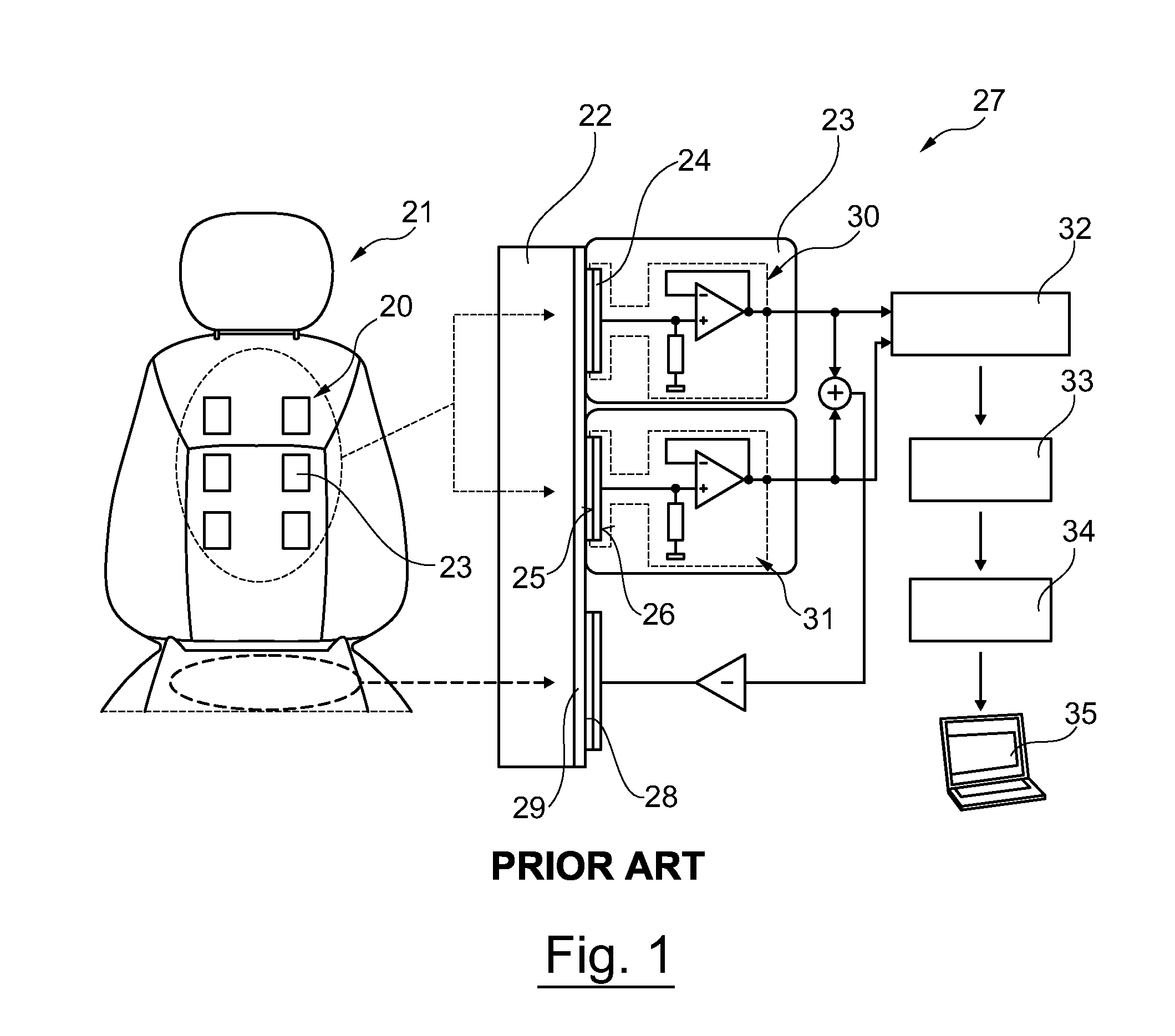
[0033]FIG. 1 schematically depicts a sensor array 20 and a seat 21 for a vehicle, for a contactless electrocardiographic measurement on a person 22, according to the prior art. It is possible to identify that the sensor array consists of a matri...


PUM

PropertyMeasurementUnit
areaaaaaaaaaaa
heightaaaaaaaaaa
widthaaaaaaaaaa

Abstract

A sensor for a contactless electrocardiographic measurement on a person includes a carrier for fastening the sensor on an object, such as a vehicle seat, and at least one electrically flat electrode mounted to the carrier by an elastic element. An inflatable bellows is disposed between the carrier and the electrode, inflation of the bellows deflecting the elastic element and increasing a distance between the electrode and the carrier to thereby urge the electrode toward a person seated on the seat.

Description

CROSS-REFERENCE TO RELATED APPLICATIONS[0001]This application claims foreign priority benefits under 35 U.S.C. §119(a)-(d) to DE 10 2013 216 682.6 filed Aug. 22, 2013, which is hereby incorporated by reference in its entirety.TECHNICAL FIELD[0002]The present invention relates to a sensor for a contactless electrocardiographic measurement on a person. Furthermore, the invention relates to a sensor array equipped with a plurality of sensors, and to a seat or couch in a vehicle, equipped with a sensor array.BACKGROUND[0003]Measuring the electric potential or the electric field strength on the skin of a person by means of electrocardiographic sensors forms the basis for many medical diagnostic methods. By way of example, this allows an electrocardiogram (EKG) to be recorded or the heart rate to be established from the measured electric potentials.[0004]In conventional methods for measuring the electric potential on the skin, said electric potential is registered by electrodes which are ...

Claims


Application Information

Patent Timeline
Patent Type & Authority Applications(United States)
IPC IPC(8): G01R1/067F04B45/027A61B5/00G01L1/00A61B5/0408B60N2/90
CPCG01R1/06794G01L1/00F04B45/027A61B5/6891A61B5/0408F04B45/02A61B5/25A61B5/26A61B5/28
Inventor LEM, JEROENEILEBRECHT, BENJAMINMATHISSEN, MARCELLINDNER, ACHIMVOGT, RAINERWALTER, MARIANLEONHARDT, STEFFEN
Owner FORD GLOBAL TECH LLC
Learn More