Oil mist separator

Active Publication Date: 2015-02-26
TOYOTA BOSHOKU KK
View PDF25 Cites 21 Cited by
  • Summary
  • Abstract
  • Description
  • Claims
  • Application Information

AI Technical Summary

Benefits of technology

The present invention provides an oil mist separator that improves oil separation efficiency and productivity. It includes a cylinder head cover and a baffle plate made of resin, which prevents the entry of oil splashes and separates the oil component from the blow-by gas. The invention also includes an oil inflow preventive board that stops the entry of oil into the introduction port. The baffle plate has a simple structure and a cylinder head cover with a nozzle hole has enhanced sealability. The circumferential wall is integrally formed with the baffle plate and has a double structure for rigidity and lightweight. The welding jig can easily and reliably fix the baffle plate onto the welding jig during vibration welding.

Problems solved by technology

As a result, the blow-by gas is in danger of flowing not only through the nozzle hole, but also into the gap, thereby causing the deterioration in oil separation efficiency.
When the partition wall is integrally molded with a cylinder head cover made of a resin in order not to create such a gap, the shape of the cylinder head cover becomes complicated, resulting in a complicated structure of a mold for molding this.

Method used


Image

  • Oil mist separator
  • Oil mist separator
  • Oil mist separator

Examples


examples

[0037]Hereinafter, the present invention will be explained in detail by way of Examples with reference to the drawings.

(1) Construction of Oil Mist Separator

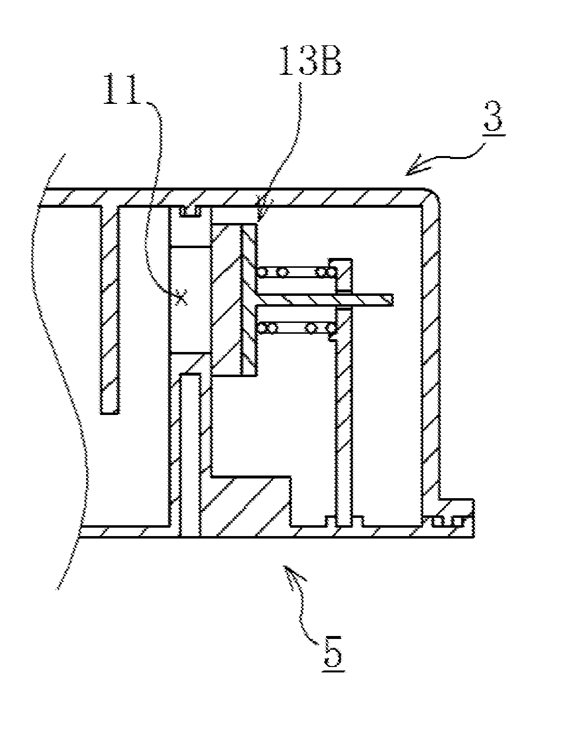
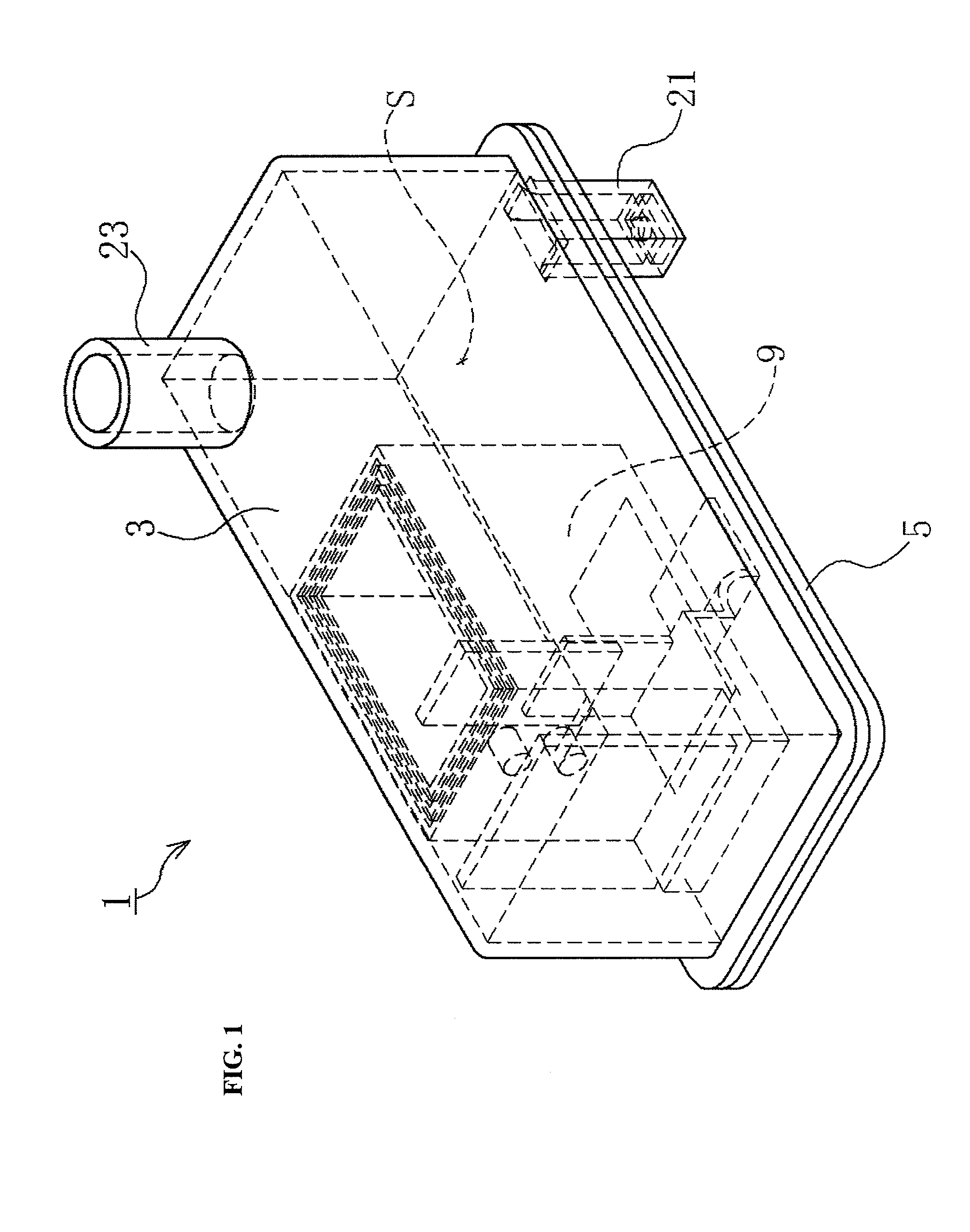
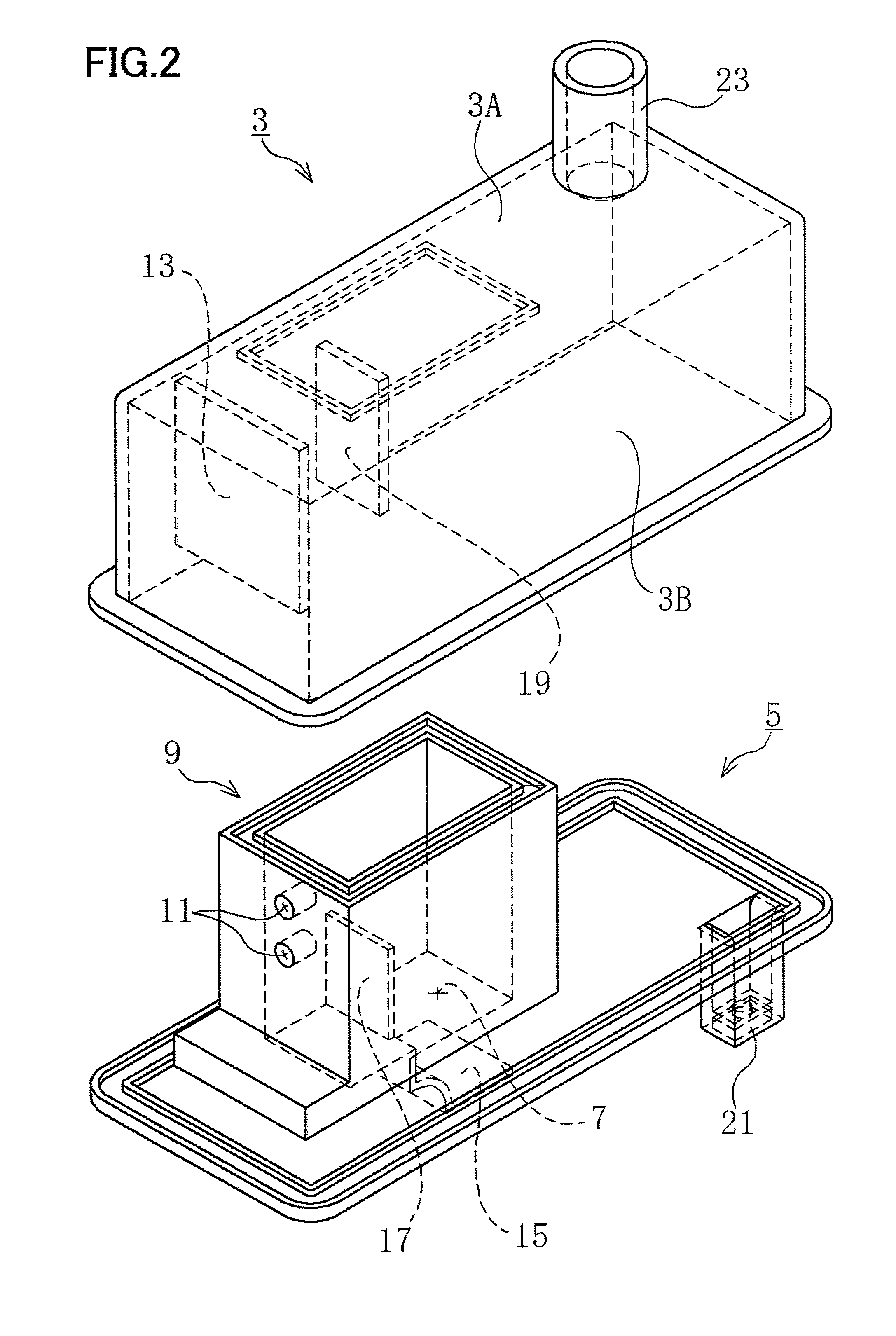
[0038]An oil mist separator 1 according to this Example is arranged in a cylinder head part of a vehicle engine. The oil mist separator 1 separates a mist oil component from a blow-by gas generated in the engine. As shown in FIGS. 1 to 6, the oil mist separator 1 includes a cylinder head cover 3 and a baffle plate 5. These cylinder head cover 3 and baffle plate 5 are made of a resin, and formed by injection molding.

[0039]As shown in FIG. 2, the cylinder head cover 3 includes an upper wall 3A and a side wall 3B, and has an elongated box-like shape in which the bottom face is opened. Also, the baffle plate 5 is formed in an elongated plate shape so as to block the bottom face of the cylinder head cover 3. The baffle plate 5 is welded, at its circumferential edge part, with the lower end of the side wall 3B of the cylinder head cov...


PUM

PropertyMeasurementUnit
Circumferenceaaaaaaaaaa

Abstract

The oil mist separator includes a cylinder head cover made of a resin and having a form in which the bottom face is opened; and a baffle plate made of a resin and arranged so as to block the bottom face of the cylinder head cover. An introduction port which introduces the blow-by-gas, a circumferential wall having such a form as to extend upward from the circumference of the introduction port, and an oil inflow preventive board arranged on the lower side of the introduction port are formed in the baffle plate. The circumferential wall is welded, at its upper end part, with the cylinder head cover . Also, a nozzle hole through which the blow-by gas flows is formed in the circumferential wall. A separating means (for example, collision board) which separates the oil component from the blow-by gas having passed through the nozzle hole is provided on the downstream side of the nozzle hole.

Description

CROSS-REFERENCE TO RELATED APPLICATIONS[0001]The present application claims priority under 35 U.S.C. §119 of Japanese Application No. 2013-172636 filed on Aug. 22, 2013, the disclosure of which is expressly incorporated by reference herein in its entirety.BACKGROUND OF THE INVENTION[0002]1. Technical Field[0003]The present invention relates to an oil mist separator, and, more specifically, to an oil mist separator which can enhance the sealability around a nozzle hole, thereby improving the oil separation efficiency and can also improve the productivity.[0004]2. Description of Related Art[0005]Oil mist separators having a gas-liquid separation structure which separates an oil component in a blow-by gas in a flow path for a blow-by gas formed within a cylinder head cover are generally known as conventional oil mist separators. As such oil mist separators, for example, providing a partition wall including a nozzle hole formed within a flow path for a blow-by gas and colliding the blow...

Claims


Application Information

Patent Timeline
IPC IPC(8): B01D45/08F01M13/04
CPCF01M13/04B01D45/08F01M13/0011F01M2013/0433F01M2013/0438F01M2013/0461B01D45/16B01D45/12B01D50/20
Inventor WAKABAYASHI, KEISUKE
Owner TOYOTA BOSHOKU KK
Why Eureka
Try Eureka