Methods of manufacturing piezoelectric element, liquid ejecting head, and ultrasonic transducer
a piezoelectric element and liquid ejecting head technology, applied in the direction of electrical transducers, piezoelectric/electrostrictive/magnetostrictive devices, printing, etc., can solve the problems of easy formation of pinpoint unevenness, and damage to the piezoelectric layer. , the effect of reducing the damag
- Summary
- Abstract
- Description
- Claims
- Application Information
AI Technical Summary
Benefits of technology
Problems solved by technology
Method used
Image

Examples
embodiment 1
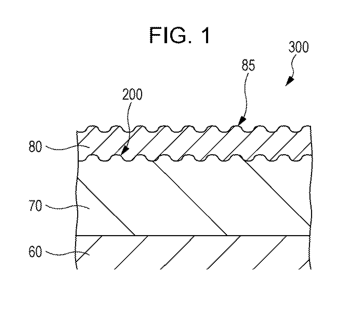
[0025]FIG. 1 is a cross-sectional view illustrating a piezoelectric element according to Embodiment 1 of the invention.
[0026]As illustrated in FIG. 1, a piezoelectric element 300 includes a first electrode 60, a piezoelectric layer 70, and a second electrode 80. According to the embodiment, although the embodiment is described with the first electrode 60 being provided on one side of the piezoelectric layer 70 and the second electrode 80 being provided on the other side of the piezoelectric layer 70, the invention is not limited thereto. For instance, the first electrodes 60 and the second electrodes 80 may be separately provided on one surface of the piezoelectric layer 70. In addition, the first electrodes 60 and the second electrodes 80 may be formed throughout the entire surface of the piezoelectric layer 70, or a portion thereof may be removed.
[0027]Here, the piezoelectric layer 70 is made of a piezoelectric material of an oxide having a polarization structure, for example, a c...
embodiment 2
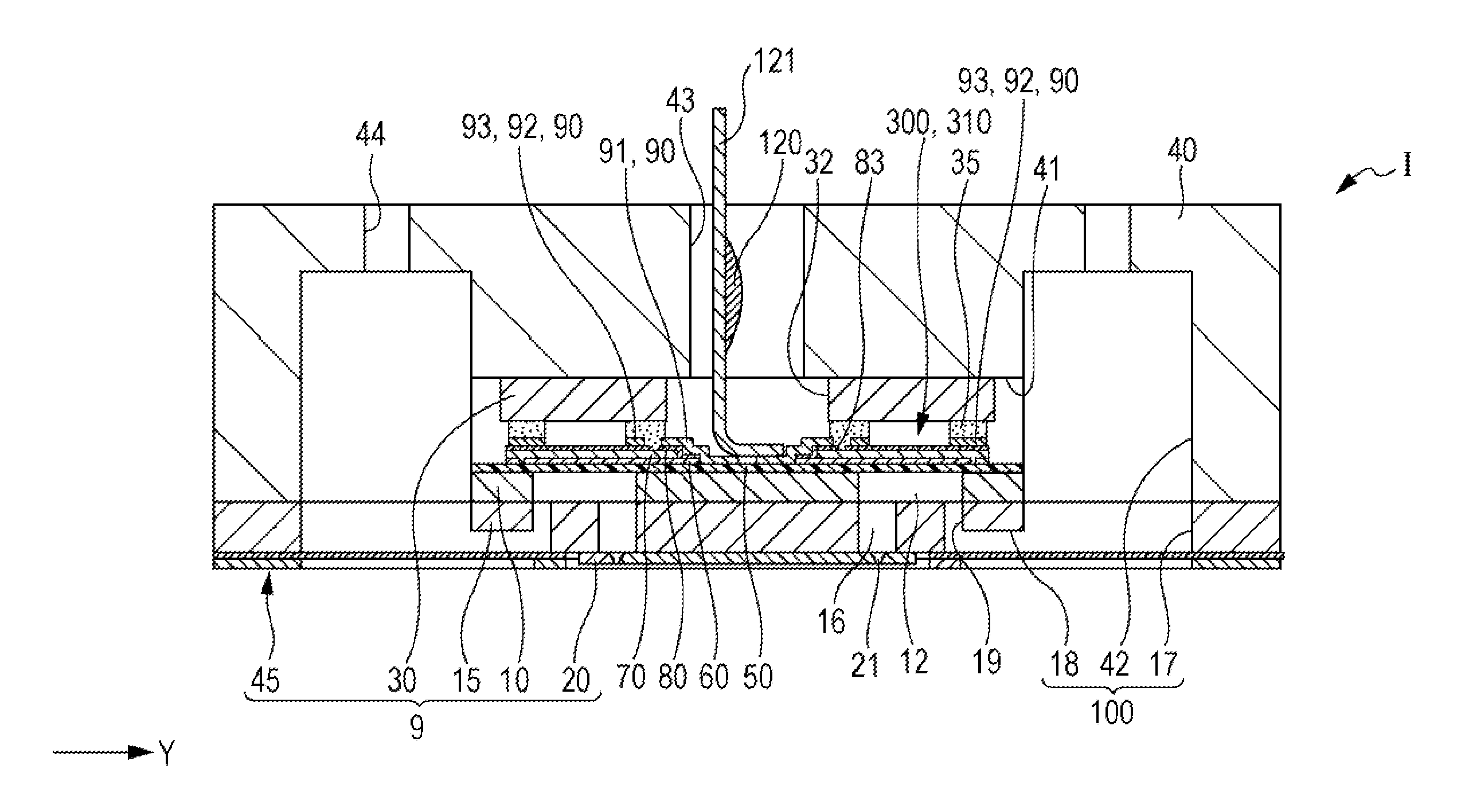
[0043]FIG. 3 is an exploded perspective view illustrating an ink jet recording head which is an example of a liquid ejecting head according to Embodiment 2 of the invention. FIG. 4 is a cross-sectional view illustrating an ink jet recording head according to Embodiment 2. FIG. 5 is an enlarged view illustrating a main section of FIG. 4.
[0044]As illustrated, an ink jet recording head I (which is an example of a liquid ejecting head according to the embodiment) includes a plurality of members such as a head main body 9 and a case member 40, and the plurality of members are joined by a bonding agent or the like. According to the embodiment, the head main body 9 includes a channel forming substrate 10, a communication substrate 15, a nozzle plate 20, a protection substrate 30, and a compliance substrate 45.
[0045]In the channel forming substrate 10 configuring the head main body 9, pressure generating chambers 12 which are separated by a plurality of partitions are arranged in parallel b...
embodiment 3
[0075]Hereinafter, an ultrasonic sensor according to an embodiment of the invention is described. In addition, the embodiment described below is not intended to limit the invention recited in the claims, and not all the configurations of the embodiment are essential for the solution of the invention. Further, the same elements in the embodiment described above are denoted by the same reference numerals, and repeated description is omitted.
[0076]According to the embodiment, transmission and reception of ultrasonic waves are performed by using an electro-acoustic transducer using a piezoelectric effect. The electro-acoustic transducer is a piezoelectric element and uses conversion of electrical energy into mechanical energy (inverse piezoelectric effect) at the time of generating ultrasonic waves so that the change caused by contraction and expansion of the piezoelectric layer excites and vibrates the diaphragm such that ultrasonic waves are generated. Accordingly, in this case, the p...
PUM
| Property | Measurement | Unit |
|---|---|---|
| Piezoelectricity | aaaaa | aaaaa |
Abstract
Description
Claims
Application Information
 - R&D
- Intellectual Property
- Life Sciences
- Materials
- Tech Scout
- Unparalleled Data Quality
- Higher Quality Content
- 60% Fewer Hallucinations
Browse by: Latest US Patents, China's latest patents, Technical Efficacy Thesaurus, Application Domain, Technology Topic, Popular Technical Reports.
© 2025 PatSnap. All rights reserved.Legal|Privacy policy|Modern Slavery Act Transparency Statement|Sitemap|About US| Contact US: help@patsnap.com