Measurement method for aviation-specific proximity sensor

Active Publication Date: 2015-02-19
SHAO ZHIBIAO +1
View PDF4 Cites 0 Cited by
  • Summary
  • Abstract
  • Description
  • Claims
  • Application Information

AI Technical Summary

Benefits of technology

The present invention provides an analog-digital mixed measurement method for an aviation-specific IPS. This method has the advantages of two conventional methods: ensuring that the system works within a standard temperature range, improving measurement stability, reliability, and real-time performance, while omitting floating point calculation and saving hardware resources. The method utilizes a specific calculation method for a 2-dimensional look-up table, an evaluation method for quantizing error of the look-up table method, and a method for greatly compressing the look-up table. By effectively compressing the look-up table and removing points where it may not be necessary, the size of the table is decreased. The present invention has applications in aviation systems such as landing gears, passenger and cargo doors, flaps, and thrust reversers, improving MTBF and increasing market share of IPS products and secondary developed products thereof. The multi-dimensional look-up table compression method is able to effectively reduce size and cost of related control detection systems, improving system stability, and providing extensive application prospect, economic benefit, and social benefit.

Problems solved by technology

However, high current driving and controlling methods of the sensor cannot meet the general electromagnetic compatibility standards in aviation field.
Therefore, the industrial sensor is not suitable for the field of aviation.
However, due to a large temperature drift of the resistance inside the sensor, an operating temperature range of the measuring system is small.
However, the digital measurement method is poor in stability, liable to be affected by external electromagnetic annoyance, and insufficient in real-time performance

Method used


Image

  • Measurement method for aviation-specific proximity sensor
  • Measurement method for aviation-specific proximity sensor
  • Measurement method for aviation-specific proximity sensor

Examples


Embodiment Construction

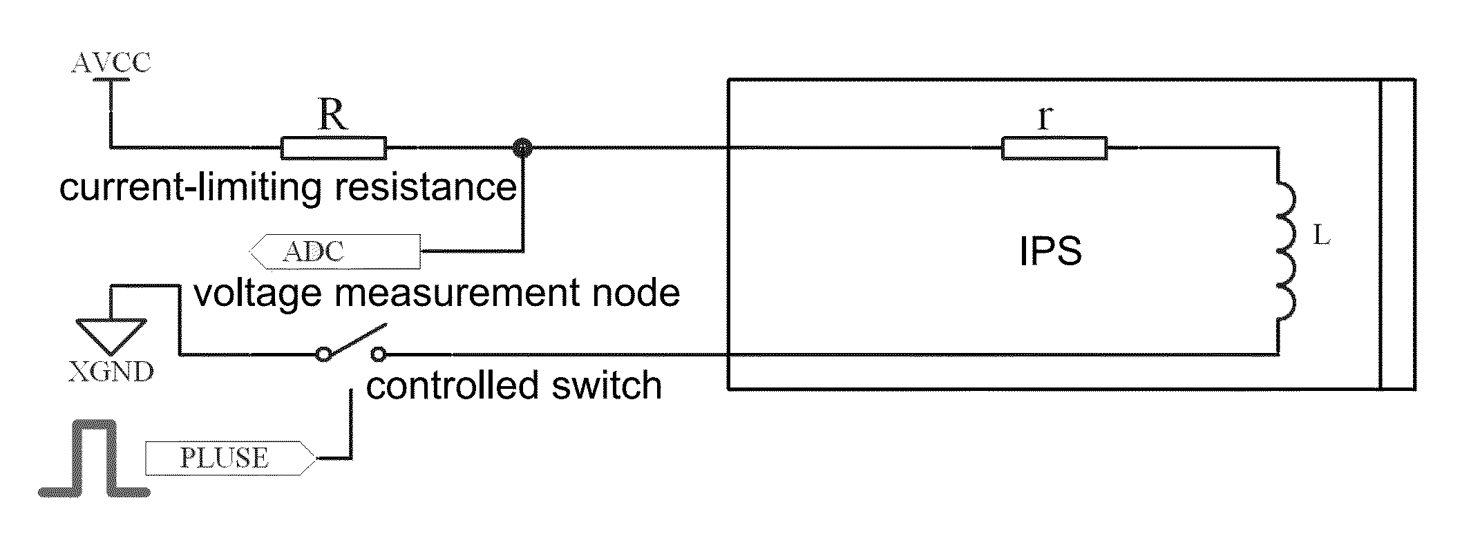
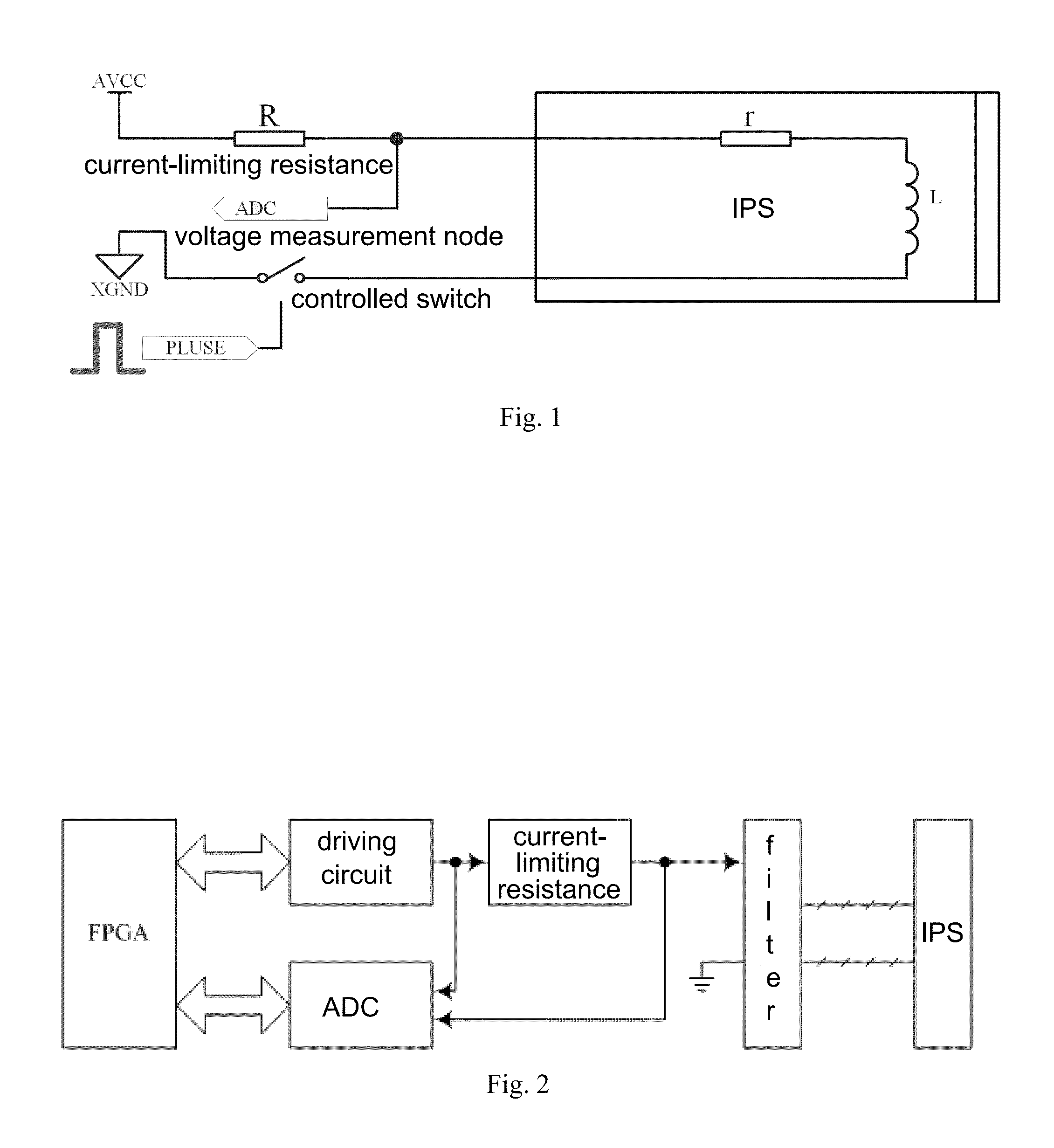
[0065]Referring to the drawings, the present invention is further illustrated.

[0066]According to the present invention, an internal circuit structure of an IPS is simple, which is formed by a group of metal winding wires. Referring to the FIG. 1, an equivalent circuit model thereof is formed by an internal resistance r in an induction coil and an inductance L connected in series (a parasitic capacitance is ignored). The internal resistance r increases when environmental temperature increases, and a value of the inductance L relates to a distance between the IPS and a metal target. If an external metal target is moving towards the IPS, electromagnetic field distribution around the IPS is greatly changed, and an equivalent induction of the IPS is increased. By driving and detecting an induction value, whether the external metal target is moving towards the IPS is able to be judged.

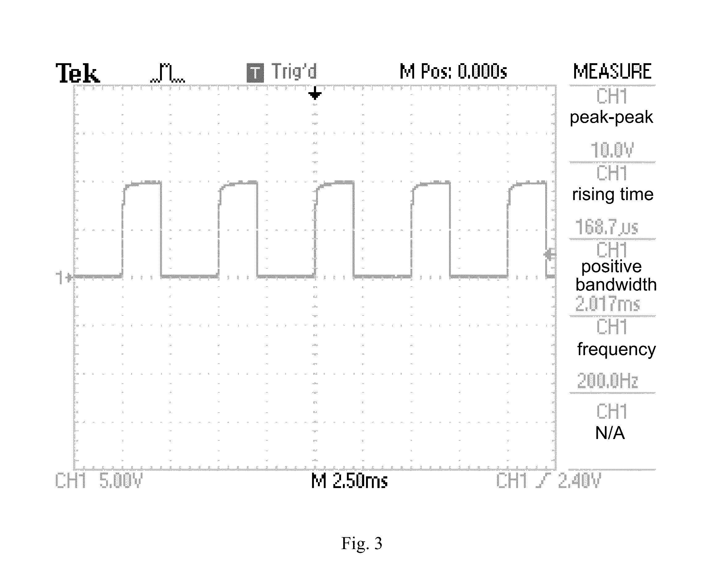
[0067]For example, an induction value of a product of Crouzet changes from 4.5 mH (far) to 5.5 mH (close)...


PUM


Abstract

A measurement method for an aviation-specific inductive proximity sensor (IPS for short) includes steps of: 1) building a measurement circuit, wherein an IPS comprises an internal resistance r and an inductance L; 2) building a look-up table, wherein the step 2) specifically comprises steps of: sampling a first voltage measured value U1 corresponding to a first constant delay time T1 with the ADC; sampling a second voltage measured value U2 corresponding to a second constant delay time T2 with the ADC; then obtaining voltage discharge formulas U1(T1, R, r, L) and U2(T2, R, r, L) of an r-L circuit; and 3) compressing the look-up table, utilizing the compressed look-up table for calculation during measurement. The present invention ensures that the system works within a standard temperature range, and improves measurement stability, reliability, and real-time performance. Furthermore, there is no floating point calculation, which saves CPU or MCU hardware resources.

Description

CROSS REFERENCE OF RELATED APPLICATION[0001]This is a U.S. National Stage under 35 U.S.C. 371 of the International Application PCT / CN2012 / 072799, filed Mar. 22, 2012.BACKGROUND OF THE PRESENT INVENTION[0002]1. Field of Invention[0003]The present invention belongs to a field of sensors, relates to driving and detection methods for a passive sensor, and more particularly to driving and detection methods for an aerospace inductive proximity sensor (IPS for short), and an optimization method for calculating inductance values by table look-up, which are in particular applicable to table compression of sampling and calculating a charge-discharge curve of an r-L circuit by table look-up.[0004]2. Description of Related Arts[0005]Because a non-contact IPS has higher reliability and mean time between failures (MTBF for short) than a mechanical displacement switch, the non-contact IPS is increasingly frequently used in aviation electromechanical systems such as various types of aircraft landin...

Claims


Application Information

Patent Timeline
IPC IPC(8): G01B7/00G01R27/26
CPCG01R27/2611G01B7/003G01D5/243
Inventor SHAO, ZHIBIAOGUO, YIXIN
Owner SHAO ZHIBIAO
Why Eureka
Try Eureka