System and method for providing power via a spurious-noise-free switching device

a switching device and spurious noise technology, applied in the direction of power conversion systems, dc-dc conversion, instruments, etc., can solve the problems of reducing power efficiency, increasing size and cost, and reducing performance, so as to eliminate spurious noise

Inactive Publication Date: 2015-02-19
IOWA STATE UNIV RES FOUND INC
View PDF7 Cites 5 Cited by
  • Summary
  • Abstract
  • Description
  • Claims
  • Application Information

AI Technical Summary

Benefits of technology

The invention provides a method for generating power from a switching device by generating an oscillating signal in the form of a series of pulse trains and randomly changing the switching frequency, or the on-time, or both. The method also includes changing from one frequency to another at the end of a pulse train and starting the second frequency with the first pulse train to avoid duty cycle distortion. Additionally, the method ensures that spurious noise is eliminated by satisfying a specific condition. The technical effect of this invention is to optimize power generation from a switching device with reduced noise and improved efficiency.

Problems solved by technology

Theoretically, the efficiency of these types of switching power converters can reach 100%, but is typically less due to non-idealities associated with the power transistors and the energy storing elements.
In many cases, this spurious output noise interferes with the load and significantly degrades its performance.
However, this strategy results in much lower power efficiency, as well as increased size and cost.
Moreover, as switching frequencies of switching power converters increase, for example into the 3 MHz to 10 MHz range, in order to reduce the size of the passive components needed, and to improve the switching converter's transient performance, linear regulators become less effective in filtering the spurious noise, due to poor power supply rejection at frequencies beyond 1 MHz.
Typically, this approach includes using multi-phase regulators, which can significantly increase the cost and implementation complexity, due to the large number of passive components required and the high accuracy of the timing relationship needed between different switching phases.
Active ripple cancellation, using different classes of linear amplifiers in parallel with the switching power converter, has also been explored, but this method generally results in poor efficiency due to the high bandwidth required in these amplifiers, as well as the significant ripple current they must provide to cancel out the spurious noise.
While this technique may be able to reduce spurious noise, it may also result in large and broad-band increases in the noise floor, which, in turn, may necessitate the use of additional linear regulators anyway.
While the required linear regulators in these cases generally have relaxed power supply rejection requirements, from a power efficiency perspective, this approach is not an improvement over already existing schemes.

Method used


Image

  • System and method for providing power via a spurious-noise-free switching device
  • System and method for providing power via a spurious-noise-free switching device
  • System and method for providing power via a spurious-noise-free switching device

Examples


Embodiment Construction

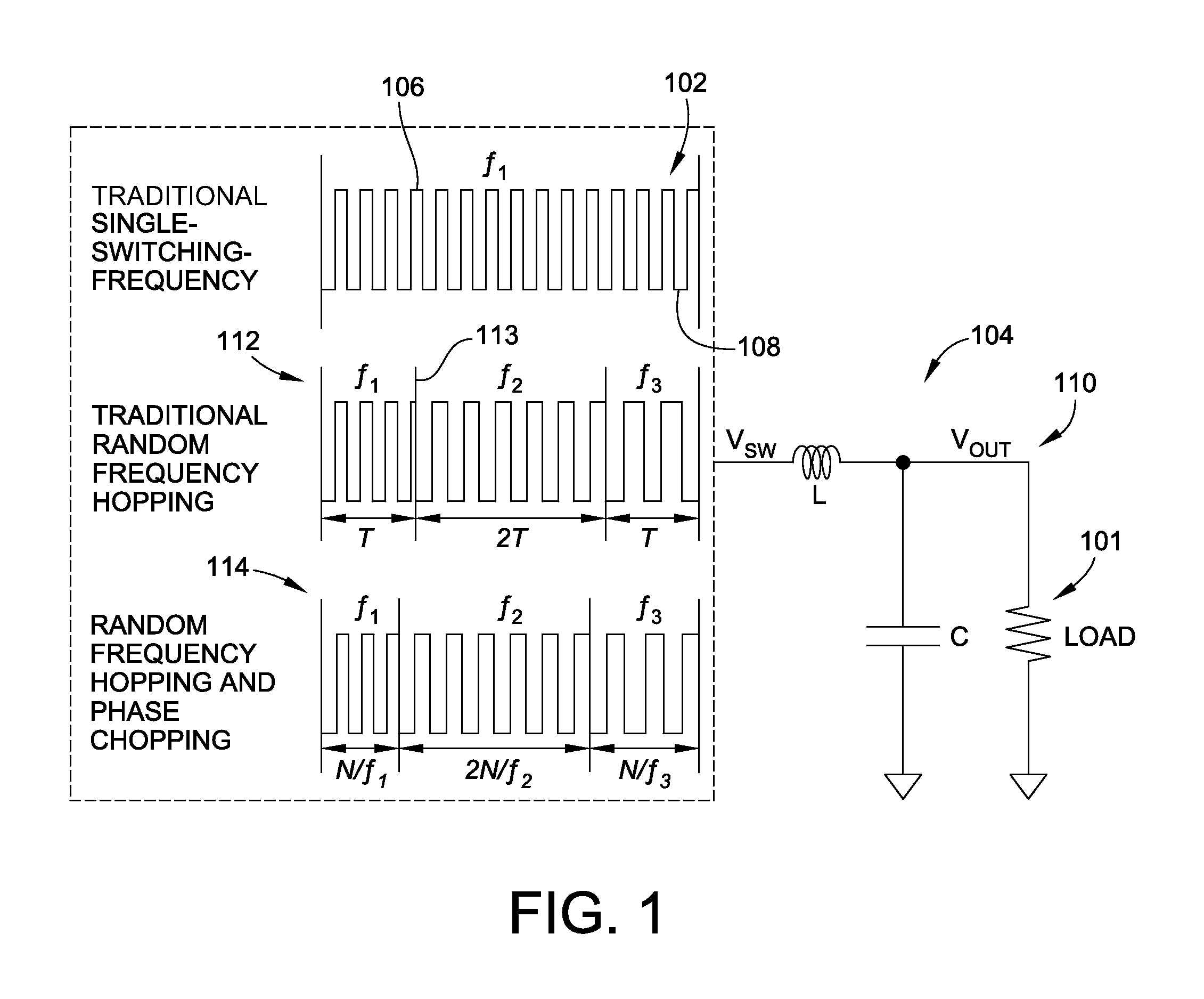
[0034]Embodiments of the invention described herein disclose a new method for generating spurious-noise-free power from a switching converter, wherein the method combines random frequency hopping with random phase chopping to control the switching power converter. In order to understand the process underlying the embodiments of the invention, it is useful to remember that, in the steady-state, the spectrum of a switching converter output supplying a load 101 can be deduced using the diagram of FIG. 1, where a pulse train 102 at the switching frequency f1 is applied to a circuit 104, such as a low-pass LC filter, for example. This pulse train 102 alternates between the input power source level 106 and ground 108 with a duty-cycle determined by the voltage level required at the output 110 of the converter.

[0035]In traditional single-switching-frequency power converters, the pulse train 102 is periodic, and the spectrum of this periodic pulse train will have spurs at the switching freq...


PUM


Abstract

A switching power converter includes a converter input configured to receive a first electrical signal, and a converter output configured to supply a second electrical signal at a desired voltage. The switching power also converter includes a control circuit for controlling one or more switches to produce the desired voltage. The control circuit is configured to control the one or more switches using one of pulse-frequency modulation and pulse-width modulation, such that an oscillating signal is generated using a combination of random frequency-hopping and random phase-chopping.

Description

CROSS-REFERENCE TO RELATED PATENT APPLICATION[0001]This patent application is a Division of co-pending U.S. patent application Ser. No. 13 / 397,251, filed on Feb. 15, 2012, which claims the benefit of U.S. Provisional Patent Application No. 61 / 444,459, filed on Feb. 18, 2011, the entire teachings and disclosures of which are incorporated herein by reference thereto.FIELD OF THE INVENTION[0002]This invention generally relates to a system and method for providing electrical power from a switching device, and more specifically to a system and method for providing electrical power without spurious noise from a switching device.BACKGROUND OF THE INVENTION[0003]Switching power converters are commonly used to generate regulated power supply rails out of unregulated energy sources. The generated power supply rails are used to power a variety of circuit loads. There are a variety of different types of switching power converters, such as buck converters, boost converters, buck-boost converters...

Claims


Application Information

Patent Timeline
Patent Type & Authority Applications(United States)
IPC IPC(8): H02M3/158
CPCH02M3/158H02M3/156
Inventor FAYED, AYMAN ADELTAO, CHENGWU
Owner IOWA STATE UNIV RES FOUND INC
Why Eureka
Try Eureka