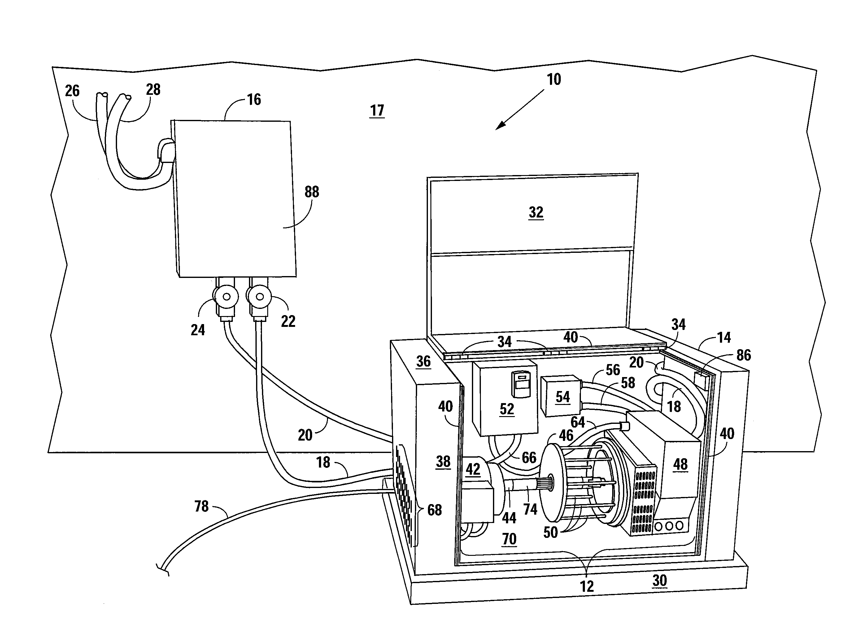
System for Generating and Recovering Energy
a cogeneration system and energy technology, applied in the field of alternative energy cogeneration systems, can solve the problems of inconvenient and potentially dangerous for consumers, noisy, and difficult to manage and pay utility bills, and achieve the effects of reducing the dependency on fossil based fuels, reducing the carbon footprint, and high quality
- Summary
- Abstract
- Description
- Claims
- Application Information
AI Technical Summary
Benefits of technology
Problems solved by technology
Method used
Image
Examples
embodiment 300
[0054]Referring now to FIG. 6, alternative embodiment 300 of the generator portion (without housing) of a renewable energy assembly is shown. Alternative embodiment 300 is comprised of generator 310 contained within frame 312. Panels (not shown) making a housing (not shown) are integrated into frame 312 forming a volume therein. Generator 310 is comprised of motor 326, torque multiplier 334 and alternator 340, all connected in series and rotatably fixed to a shaft using couplers 332 and 337.
[0055]Output shaft 330 extends distally from motor 326 and mechanically connects motor 326 to torque multiplier 334 via coupler 332. Input shaft 338 mechanically connects torque multiplier 334 to alternator 340. Automatic voltage regulator (AVR) 342 is electronically connected to alternator 340 and maintains a constant quality and voltage level in the AC current generated by alternator 340.
[0056]Still referring to FIG. 6, both motor 326 and alternator 340 are mounted on structures within frame 31...
embodiment 700
[0062]FIG. 9 shows an alternative embodiment 700 of the present invention. With one exception, described below, the majority of components are identical to and function the same as those described with respect to cogeneration system 600, as shown in FIG. 8. The same reference numbers are used for those components for convenience. The added component is an uninterruptible power supply (UPS) and its respective UPS control box which together provide an additional path in which the power generated by generator 642 may take. The UPS of the present invention is an online / double-conversion UPS from Industronic, Model UPS-IND 1346, though other similar devices are contemplated and may be used and still be within the invention as contemplated herein.
[0063]During normal use, some power is transferred from control box 622 to UPS control box 652 and routed to UPS 656 which continuously charges a battery (not shown) therein. In the event there is an interruption of the power being transferred fr...
embodiment 800
[0064]FIG. 10 depicts an alternative embodiment 800 of the present invention. As the majority of components are identical to and function the same as those described with respect to cogeneration system 600, as shown in FIG. 8, the same reference numbers are used for those components for convenience. In this embodiment, there is no cogeneration system. Instead, the system functions independently of any electric power grid. Generator 642 is powered through the use of UPS 656 which replaces power from an electric power grid. Energy from UPS 656 is routed to the main switch box 618 via bidirectional cable 616. Electricity is then transferred to control box 622 via bidirectional cable 620. Energy generated from generator 642 is directed to home or business 646 sufficient to meet the power demands of the user. A portion of the energy generated by generator 642 is fed back via feedback loop 648 to control box 622 to continue powering generator 642 via AC driver 624. This embodiment has its...
PUM
 Abstract
Description
Claims
Application Information
 - R&D
- Intellectual Property
- Life Sciences
- Materials
- Tech Scout
- Unparalleled Data Quality
- Higher Quality Content
- 60% Fewer Hallucinations
Browse by: Latest US Patents, China's latest patents, Technical Efficacy Thesaurus, Application Domain, Technology Topic, Popular Technical Reports.
© 2025 PatSnap. All rights reserved.Legal|Privacy policy|Modern Slavery Act Transparency Statement|Sitemap|About US| Contact US: help@patsnap.com


