
Oven Appliance and a Method for Manufacturing a Cooking Chamber of an Oven Appliance

a technology of oven appliances and manufacturing methods, which is applied in the direction of domestic stoves or ranges, heating types, lighting and heating apparatus, etc., can solve the problems of difficult enamel coating application, difficult to avoid enamel coating the top panel and difficult to apply enamel evenly when the panels are assembled

Active Publication Date: 2015-02-19
HAIER US APPLIANCE SOLUTIONS INC
View PDF88 Cites 12 Cited by
  • Summary
  • Abstract
  • Description
  • Claims
  • Application Information

AI Technical Summary

Benefits of technology

The present invention provides an oven appliance with a unique design that includes a top panel, bottom panel, back panel, and pair of side panels mounted with fasteners. The fasteners ensure the panels are securely attached to each other. The oven appliance also has a cooking chamber for receiving food items for cooking. Additionally, the invention includes a method of manufacturing the cooking chamber by applying enamel and aluminum coatings onto the panels and mounting them with fasteners afterward. The technical effects of this invention include a simplified construction process, improved thermal efficiency, and enhanced aesthetic appearance.

Problems solved by technology

However, applying enamel coating to the assembled panels can be difficult.
For example, applying enamel evenly can be difficult when the panels are assembled.
However, avoiding application of enamel coating to the top panel when the panels are assembled can be difficult.
Such panel assemblies also have additional drawbacks.
For example, utilizing such panel assemblies across multiple oven appliance designs can be difficult, and such panel assemblies often require cover plates to hide unutilized features.
Such cover plates can be cosmetically unappealing.
The assembled panels can also be difficult to handle due to their bulk, and the handling difficulty can increase manufacturing time and / or cost.
In addition, bending the additional panel to form the sidewalls and the back wall of the cooking chamber can cause the cooking chamber to have rounded corners, and cooking chambers with rounded corners can appear smaller to consumers relative to cooking chambers with square corners.
Further, when the additional panel is mounted to the bottom panel, liquid can wick upwardly between the additional panel and the bottom panel and escape the cooking chamber during operating of the oven appliance, and the liquid can negatively affect operation of the oven appliance.

Method used


Image

  • Oven Appliance and a Method for Manufacturing a Cooking Chamber of an Oven Appliance
  • Oven Appliance and a Method for Manufacturing a Cooking Chamber of an Oven Appliance
  • Oven Appliance and a Method for Manufacturing a Cooking Chamber of an Oven Appliance

Examples


Embodiment Construction

[0019]Reference now will be made in detail to embodiments of the invention, one or more examples of which are illustrated in the drawings. Each example is provided by way of explanation of the invention, not limitation of the invention. In fact, it will be apparent to those skilled in the art that various modifications and variations can be made in the present invention without departing from the scope or spirit of the invention. For instance, features illustrated or described as part of one embodiment can be used with another embodiment to yield a still further embodiment. Thus, it is intended that the present invention covers such modifications and variations as come within the scope of the appended claims and their equivalents.

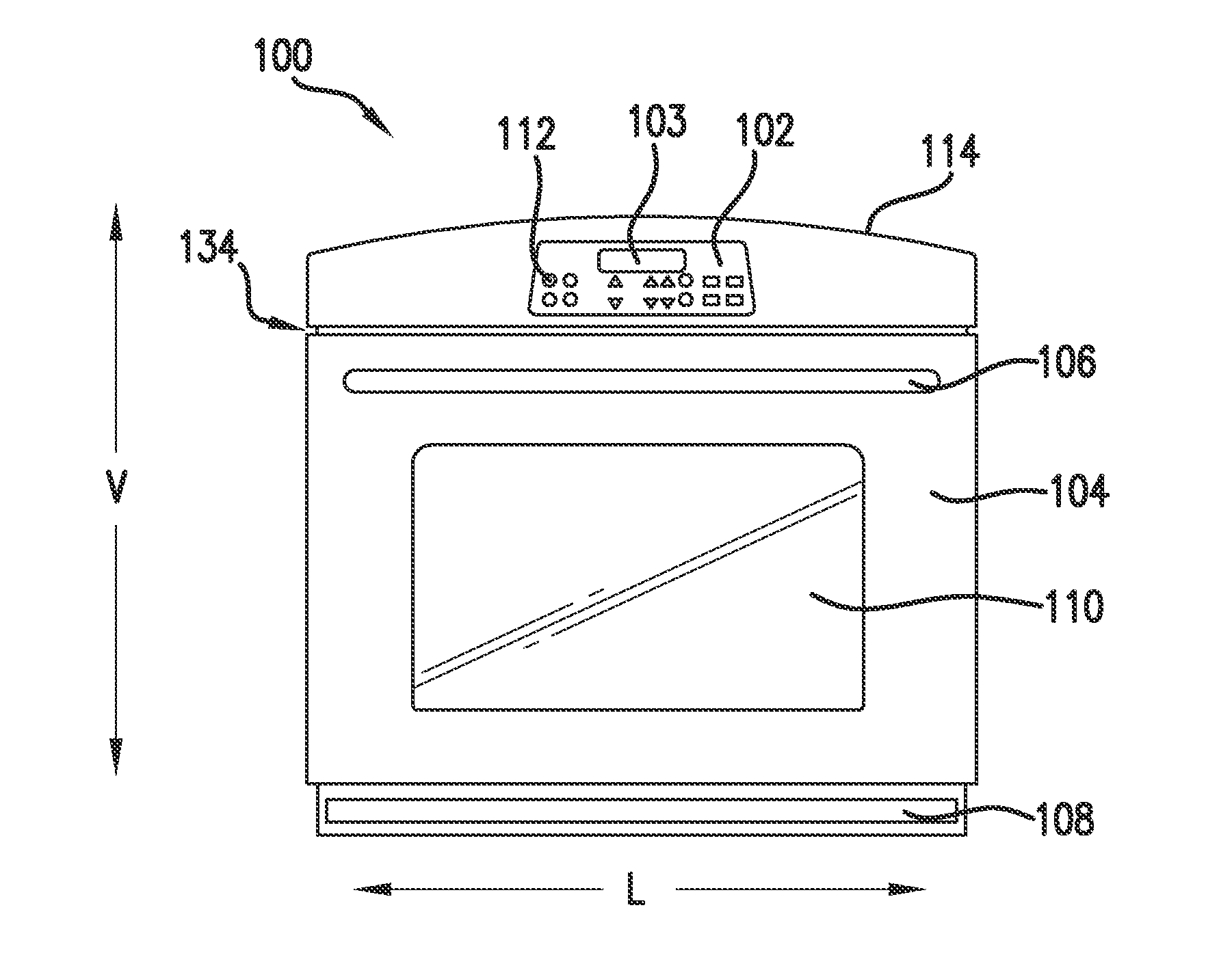
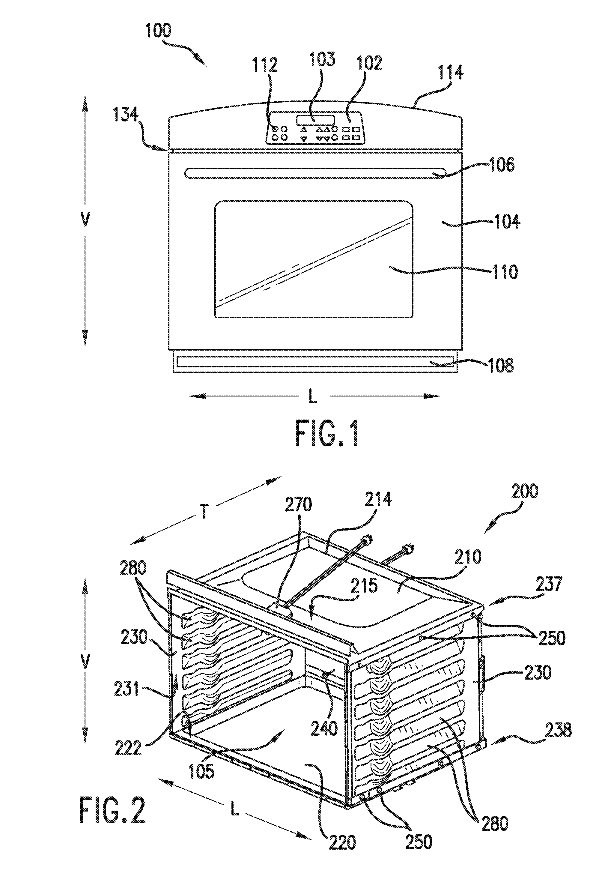
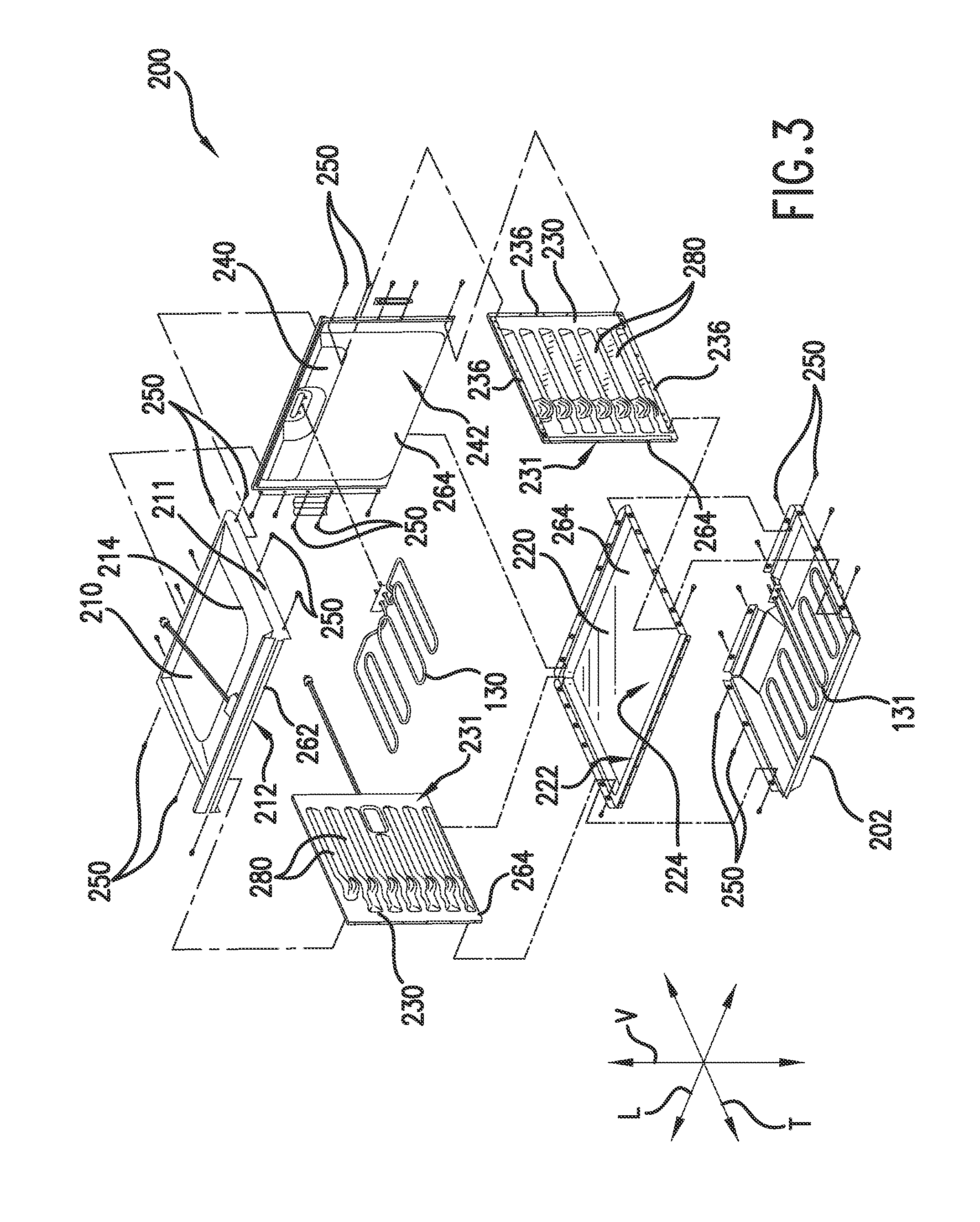
[0020]FIG. 1 provides a front, elevation view of an oven appliance 100 according to an exemplary embodiment of the present subject matter. Oven appliance 100 includes a door 104 with a handle 106 that provides for opening and closing access to a cooking cha...


PUM

PropertyMeasurementUnit
temperatureaaaaaaaaaa
heataaaaaaaaaa

Abstract

An oven appliance is provided. The oven appliance includes a top panel, a bottom panel, a back panel and a pair of side panels. The top panel, the bottom panel, the back panel and the pair of side panels are mounted to one another with a plurality of fasteners. The top panel, the bottom panel, the back panel and the pair of side panels define a cooking chamber for receiving food items for cooking.

Description

FIELD OF THE INVENTION[0001]The present subject matter relates generally to oven appliances and methods for manufacturing cooking chambers for oven appliances.BACKGROUND OF THE INVENTION[0002]Oven appliances generally include a cabinet that defines a cooking chamber for receiving food items for cooking. In certain oven appliances, the cabinet includes a top panel, a bottom panel and an additional panel that are mounted to each other to from the cooking chamber. In such oven appliances, the additional panel is bent into a c-shape to form sidewalls and a back wall of the cooking chamber.[0003]Coatings, such as an enamel coating, can be applied to panels that form the cooking chamber. To avoid damaging the enamel coating, the additional panel is preferably bent into shape and mounted to the top and bottom panels prior to applying the enamel coating to such panels. However, applying enamel coating to the assembled panels can be difficult. For example, applying enamel evenly can be diffi...

Claims


Application Information

Patent Timeline
Patent Type & Authority Applications(United States)
IPC IPC(8): F24C15/00F24C15/02
CPCF24C15/005F24C15/021F24C15/008F24C15/08Y10T29/49885Y10T29/49893Y10T29/49947
Inventor WIGGINS, WILLIAM BYRONLAWLER, BRYAN KEITHSTRONG, DEANDRE LARONGALLANT, MICHAEL DAVID
Owner HAIER US APPLIANCE SOLUTIONS INC
Learn More