
Engine operation with air system model

a technology of air system model and engine, applied in the direction of electrical control, instruments, process and machine control, etc., can solve the problems of inability to accurately identify time-consuming and expensive repairs, and inability to accurately diagnose the current engine operating sta

Active Publication Date: 2015-02-12
DEERE & CO
View PDF7 Cites 16 Cited by
  • Summary
  • Abstract
  • Description
  • Claims
  • Application Information

AI Technical Summary

Benefits of technology

The patent describes a system and method for modeling and adjusting the operation of an engine in real-time. It involves using state equations to determine the changes in the mass of the engine's system, based on various factors such as pressure drops and time constants. The system then uses these changes to adjust the engine's operating characteristics, such as air flow and fuel injection, to optimize its performance. The patent also describes the use of a computer-implemented method for this purpose. Overall, the patent aims to provide a more efficient and effective approach for controlling the operation of engines in real-time.

Problems solved by technology

Such instrumentation can be expensive, however, particularly with respect to mass-produced consumer or industrial vehicles.
Instrumentation is also sometimes prone to malfunction or other failure, which may lead to imperfect identification or understanding of current engine operating states and / or require time-consuming and expensive repairs.
Many of these models are highly non-linear and their implementation may accordingly be complex and / or computationally intensive.
Prior manifestations of air system models, however, tend to exhibit numerical instability in certain situations.
For example, when resistance to mass flow is very low (e.g., when relevant throttles and / or valves are fully or nearly fully open), small changes in pressure can result in large changes in mass flow.
In turn, such changes in mass flow may significantly affect the modeled pressure, resulting in unstable oscillations in the predicted pressures that may not accurately reflect actual engine operating conditions.
Such efforts, however, may tend both to contribute to steady state model errors and to require an excessive number of calculations for a given time interval.
The latter issue, in particular, may prevent use of such models with respect to real-time operation of an engine because the high demand for calculations tends to consume significant portions, including potentially all, of the processor capacity of the available computer resources (e.g., the engine control unit associated with a particular engine).

Method used


Image

  • Engine operation with air system model
  • Engine operation with air system model
  • Engine operation with air system model

Examples


Embodiment Construction

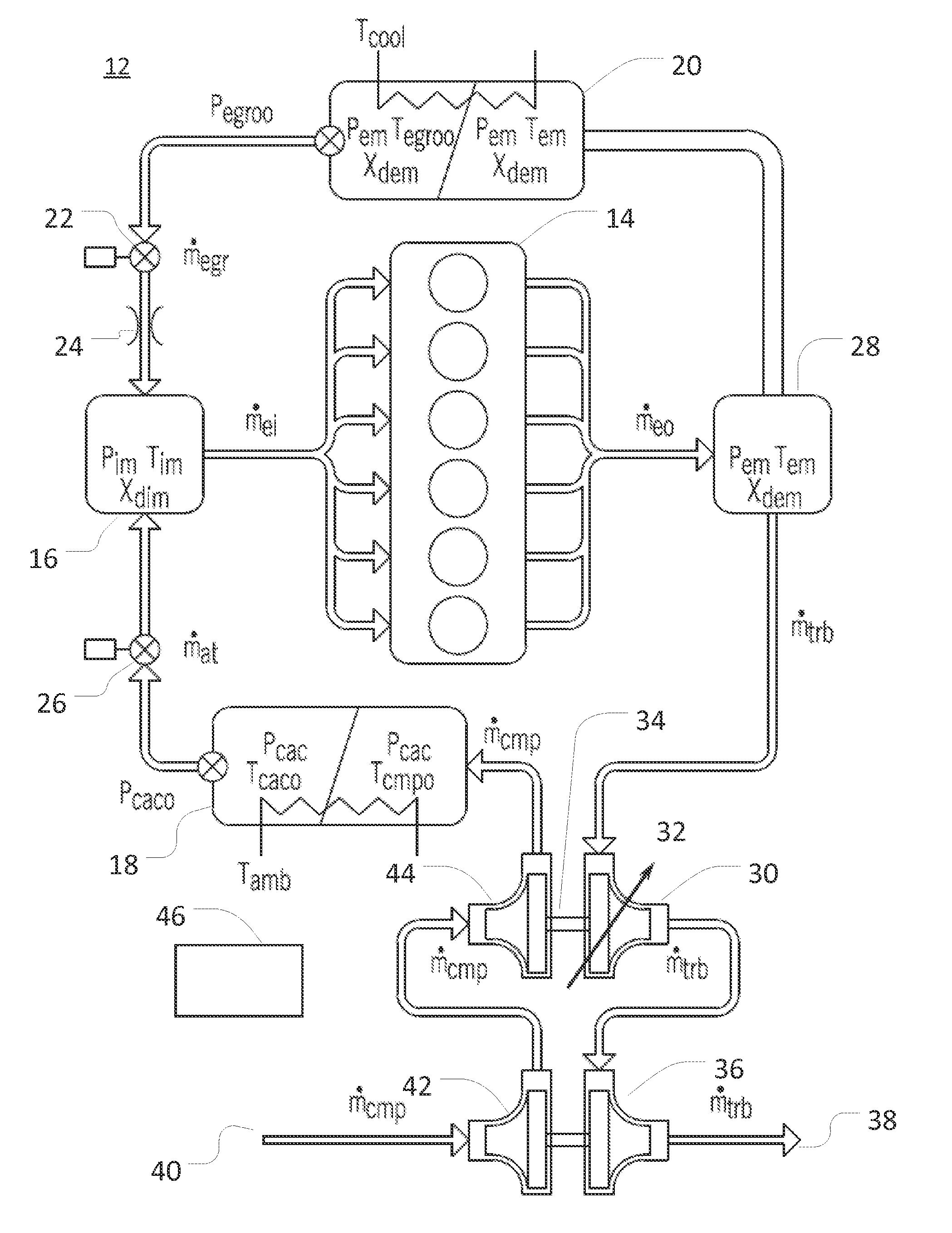
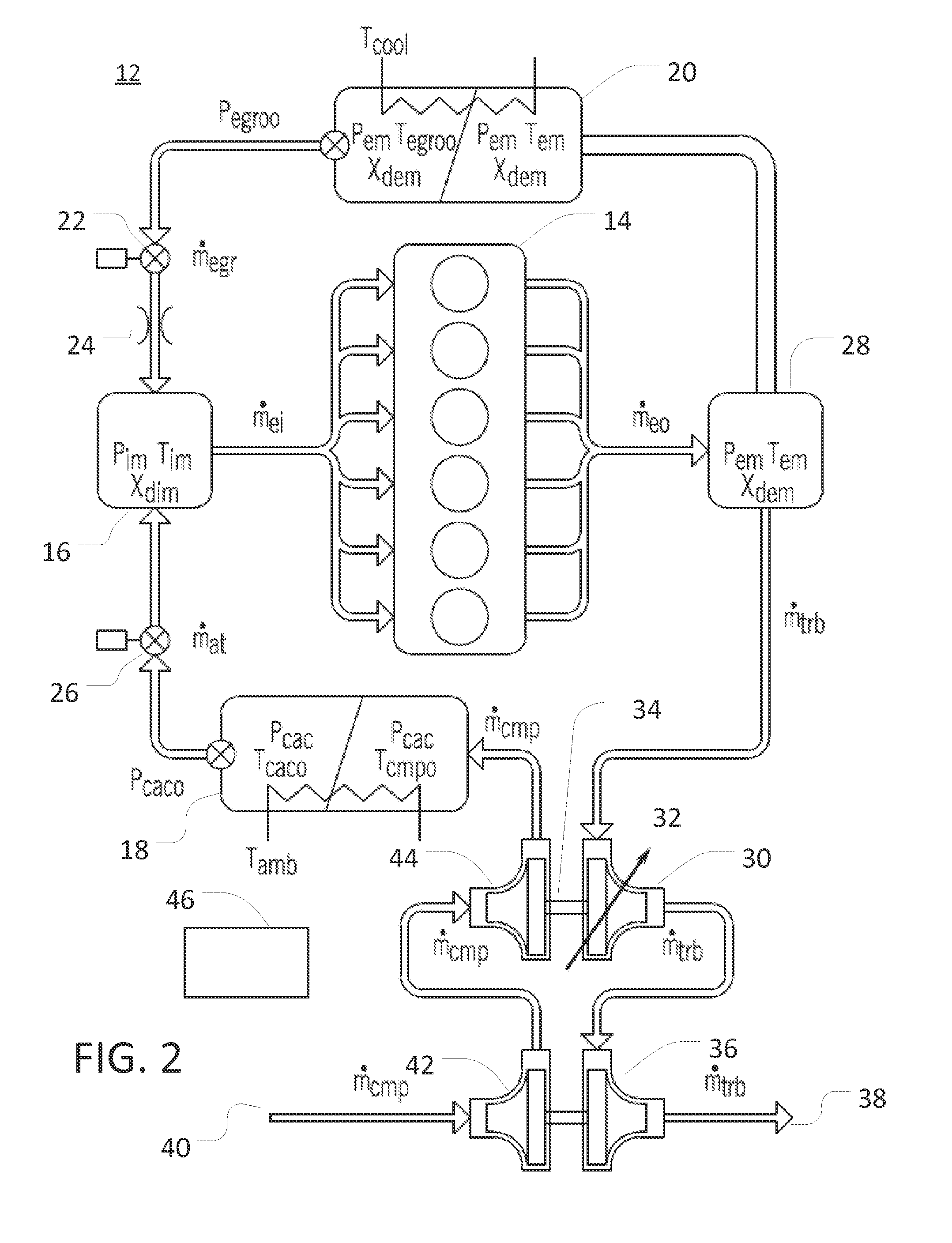
[0022]The following describes one or more example embodiments of the disclosed system and method, as shown in the accompanying figures of the drawings described briefly above. Various modification(s) to the example embodiments may be contemplated by one of skill in the art. For example, aspects of the disclosure may be additionally or alternatively implemented as a computer program product residing on a computer readable storage medium on which a plurality of instructions are stored. When executed by a processor, these instructions may cause a processor to perform various operations consistent with the disclosure herein.

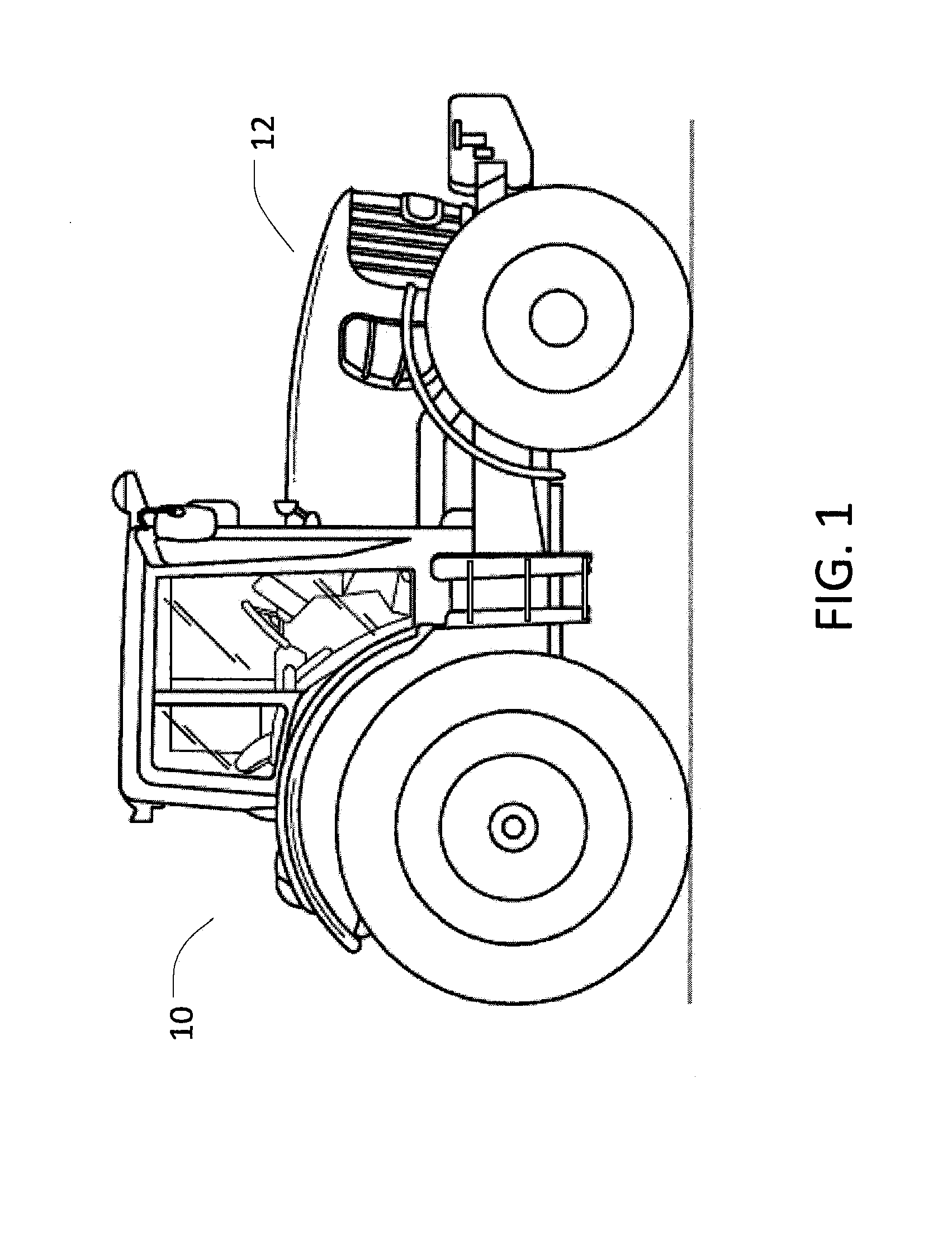
[0023]The disclosed system 10 and method 100 may be used advantageously in a variety of settings and with a variety of engine in work and / or vehicle types, including engines in work vehicles for agricultural, construction, forestry, and various other applications. Referring now to FIG. 1, for example, work vehicle 10 is depicted as a typical agricultural tractor havi...


PUM


Abstract

A system is described for modeling various states of an operating engine and the adjustment of one or more operating characteristics of the engine based upon such modeling. A representative rate of change of a system mass for an engine is determined based upon, at least in part, a first state equation. A first representative mass flow approximating a mass flow across a throttle is determined based upon, at least in part, a second state equation. A second representative mass flow approximating a mass flow across an exhaust gas recirculation valve is determined based upon, at least in part, a third state equation. Determining the first representative mass flow includes specifying a throttle time constant modifier for the second state equation. Determining the second representative mass flow includes specifying an exhaust gas recirculation valve time constant modifier for the third state equation.

Description

CROSS-REFERENCE TO RELATED APPLICATION(S)[0001]Not applicable.STATEMENT OF FEDERALLY SPONSORED RESEARCH OR DEVELOPMENT[0002]Not applicable.FIELD OF THE DISCLOSURE[0003]This disclosure relates to engine operation, and in particular to the modeling of various engine states and processes during engine operation.BACKGROUND OF THE DISCLOSURE[0004]It may be useful in various situations to model the operation of engines (e.g., gasoline or diesel engines) in order to appropriately identify, understand and / or respond to various engine states. For example, it may be useful to model pressures, temperatures, mass flow rates, and various other parameters, with respect to various points or volumes within an engine in order to inform the adjustment of operating characteristics of the engine and thereby improve power delivery, fuel efficiency, engine life, and so on. Similar information regarding engine operation may similarly be gleaned, in certain settings, from appropriate instrumentation of the...

Claims


Application Information

Patent Timeline
IPC IPC(8): F02D41/00F02D41/18G06F17/50
CPCF02D41/0002F02D41/18G06F17/50F02D41/0072F02D41/1447F02D41/1448F02B37/013F02D41/0007F02D2200/0402F02D2200/0406F02D2200/0416F02B2037/122F02B29/0406F02B37/24F02D2041/1433F02M26/23F02M26/33F02M26/02Y02T10/12Y02T10/40G06F30/00
Inventor LAHTI, JOHN L.PIPHO, MICHAEL J.
Owner DEERE & CO
Learn More