
LED Renewable Energy Lighting Unit having a Polygonal Solar Panel Configuration about a Horizontal or Vertical Pole

a renewable energy and lighting technology, applied in fixed installations, lighting and heating equipment, roadways/streets, etc., can solve the problems of long commercial and utility power outage delays of high-cost non-renewable and renewable lighting systems, and the cost of powering such non-renewable and renewable lighting can be large, and the cost of ongoing costs to pay for such non-renewable and renewable lighting can be high

Active Publication Date: 2015-02-12
WILSON OSWALD A
View PDF7 Cites 50 Cited by
  • Summary
  • Abstract
  • Description
  • Claims
  • Application Information

AI Technical Summary

Benefits of technology

The present invention is an improved solar and wind powered retrofit lighting system that can be installed on utility poles or in a solar farm. The system includes a polygonal solar panel arrangement that can be scalable in small foot print of a 250 watts solar space and will produce over 600 to 1200 watts from the solar panels. The system also includes a polish aluminum basin with upper outer rim and four corners and a screw and aluminum support brackets attached thereto for heat dissipation. The basin is secured with a screw and being sandwiched between a 5×6 inch aluminum plate and the outer die cast shell via a molded securing nut to achieve additional heat dissipation. The system produces power for 5 to 8 hours to charge battery banks that is used to power an inverter and power LED street light lamps for 12 hours at night. The system also reduces the amount of fuel used by a power or utility company to generate electricity and grid power. The C-shaped clamps with outward extending flanges are attached to the top of the half plates to seal around the utility pole to prevent any water from seeping around the pole and damaging the electronic components that are affixed to the solar panels. The system can be installed on utility poles or in a solar farm and provides a solution for limited land space.

Problems solved by technology

It is well known that non-renewable and renewable with retrofitted lighting such as those used in roadways / streets or security lights can amount to sizable costs over time, including substantial initial acquisition and installations costs of the equipment, and also the ongoing costs to pay for powering such non-renewable and renewable lighting.
These high cost non-renewable and renewable lighting systems are known to experience long commercial and utility power outage delays, where an affected geographical area is left completely in the dark.
This is not unusual for a roadway / street, town or city, commercial or government facilities, homes, businesses to be left completely in the dark due to the loss of commercial and utility power.
Also, there is a need to enhance and prolong the life cycle hours of the lighting source, which is shorten by the excessive heat generated over time with no effective way of dissipating the heat in the above mentioned high cost non-renewable and renewable lighting systems.
This causes a user to spend a lot of money replacing bulbs or lamps often.
Also, it is noted many of these non-renewable and renewable light systems provide very dim lighting.

Method used


Image

  • LED Renewable Energy Lighting Unit having a Polygonal Solar Panel Configuration about a Horizontal or Vertical Pole
  • LED Renewable Energy Lighting Unit having a Polygonal Solar Panel Configuration about a Horizontal or Vertical Pole
  • LED Renewable Energy Lighting Unit having a Polygonal Solar Panel Configuration about a Horizontal or Vertical Pole

Examples


Embodiment Construction

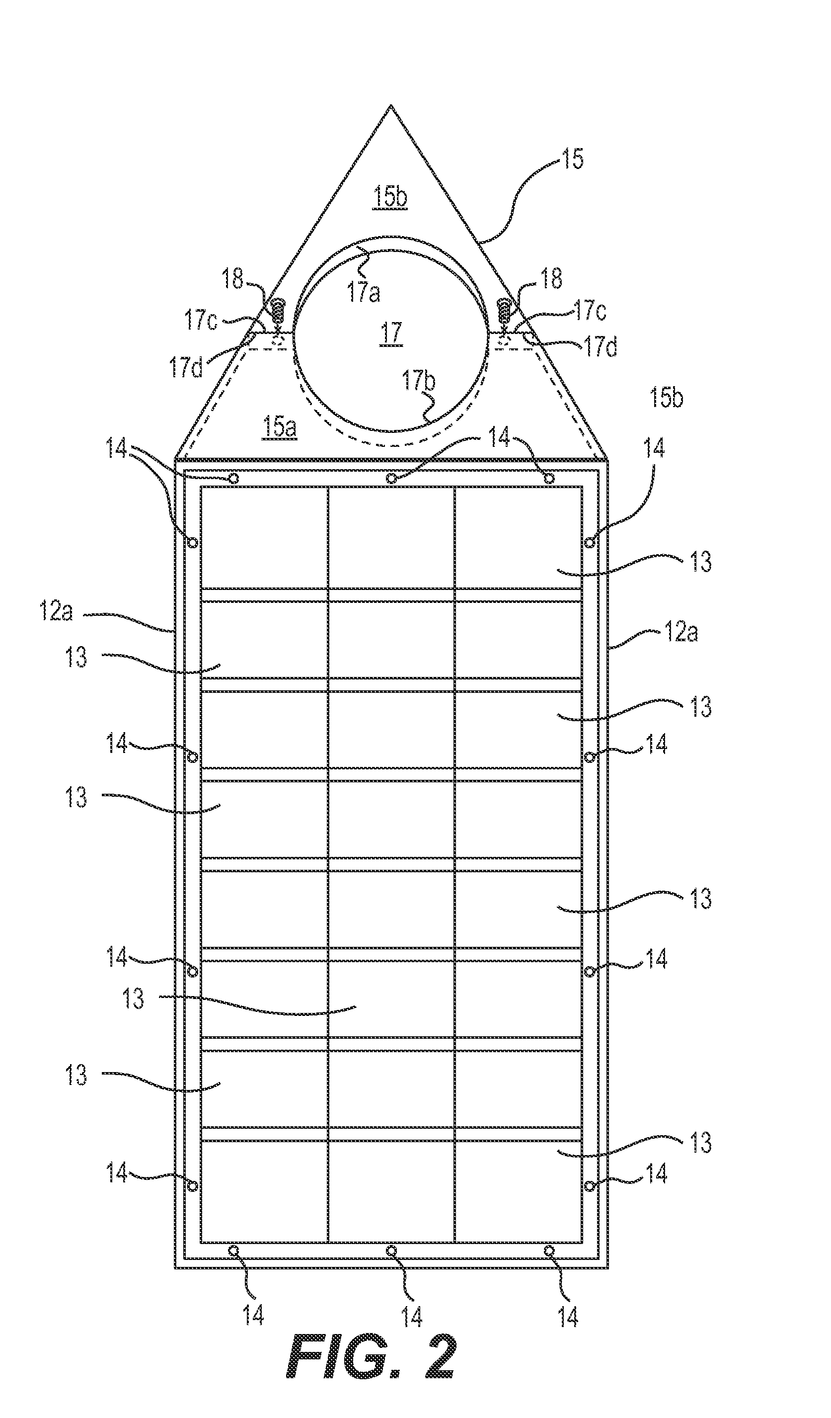
[0040]FIG. 1 illustrates a perspective view of the solar and wind powered street / roadway lighting apparatus 10 with solar panels 12 configured in a polygonal configuration according to the present invention. The polygonal configuration can be selected from the group consisting of any one of a triangle, quadrilateral, pentagon, hexagon, heptagon, octagon, enneagon, decagon, squares, rectangles, parallelograms and rhombuses. The preferred polygonal shape of the present invention is an isosceles triangle.

[0041]The solar and wind powered street / roadway lighting apparatus 10 is disposed about a utility or street light pole 11. As shown in FIG. 1, a plurality of solar panels 12 with solar cells 13 affixed thereto. These solar panels 12 with solar cells 13 secured to a polygonal support frame 14C as illustrated in FIGS. 3 and 5. A top plate with two-part halves 15a and 15b are secured to the top of the polygonal support frame 14C by screw members 16.

[0042]Note that the solar panels 12 with...


PUM


Abstract

The present invention discloses an improved renewable energy and rechargeable LED lighting unit having a roadway / street light pole with a polygonal frame member configuration disposed there about. A plurality of solar panels affixed to the polygonal configuration. The solar panels include a plurality of electrical modules that are affixed directly to an interior wall of at least one of the solar panels without interfering with the polygonal frame member when attached. A two-part closure plate arrangement are attached directly to the polygonal frame member and completely enclose and seal the plurality of electrical modules between the frame member and the at least one of the solar panels.

Description

CROSS REFERENCE TO RELATED APPLICATION(S)[0001]This instant application claims priority to U.S. Provisional Patent Application Ser. No. 61 / 864,720, filed on Aug. 12, 2013.BACKGROUND OF THE INVENTION[0002]1. Field of the Invention[0003]The present invention relates to a unique retrofit LED solar and wind powered rechargeable roadway / street light with solar panels disposed about a roadway / street light pole in a polygonal configuration. This polygonal configuration completely houses the controlling and management system electrical modules therein and being affixed to the interior of the solar panels in a compact manner as a unit that controls and manages the streetlight and a traffic light operation.[0004]In addition, the unique LED solar and wind powered rechargeable roadway / street light has an improved heat dissipation feature for enhancing and extending the life cycle hours for the LED light source while simultaneously reducing the amount of power energy consumption used.[0005]2. De...

Claims


Application Information

Patent Timeline
IPC IPC(8): F21S9/03F21S9/02F21V29/00F21S8/08
CPCF21S9/035F21S8/086F21S9/026F21Y2101/02F21V29/004F21W2131/103F21V29/2206F21S9/043F21Y2115/10Y02B20/72F21V29/50
Inventor WILSON, OSWALD A.
Owner WILSON OSWALD A
Learn More