
High Load Plastic Pallet

a high-load, plastic pallet technology, applied in the direction of packaging, transportation and packaging, containers, etc., can solve the problems of occupying a lot of space, affecting the durability of wood pallets, and affecting the use of automated packaging lines

Active Publication Date: 2015-02-12
BURK RYAN
View PDF8 Cites 8 Cited by
  • Summary
  • Abstract
  • Description
  • Claims
  • Application Information

AI Technical Summary

Benefits of technology

The present invention is a pallet design that is made of plastic or composite materials, and is stronger and lighter than traditional wood pallets. The pallet has runners that can bear loads up to 2000 pounds or more without sagging or spreading. The strength of the runners is achieved through the use of Z-girts, which provide the strength of two z-girts placed back-to-back. The runners also have lips that form a portion of the outer edge of the pallet, adding to its strength and rigidity. Additionally, cross runners or ribs may be added to further enhance the pallet's strength and rigidity. Overall, the invention provides a stronger and lighter pallet that is resistant to water, debris, and pests.

Problems solved by technology

The transport of objects from one place to another has been a challenge since ancient times. Storage of multiple objects also poses challenges.
Further, wood pallets are not as durable as plastic or metal pallets, and will swell and contract with atmospheric or working conditions, causing issues in their use for automated packaging lines.
A problem with the use of pallets for moving and storing materials is what to do with a pallet when empty.
They often are stacked but take up quite a bit of space and the stack's height is limited in order to prevent shifting and the possibility of a stack of pallets falling on someone.
Adding to the danger, many present pallet designs are heavy in order to accommodate their intended uses, making their empty-stage storage and transfer both cumbersome and expensive.
Although attempts have been made to use plastic pallets for similar loads, the designs of those pallets have been deficient in the amount of sag, and the pallet's durability and load-bearing capability.
Those pallets that adequately address sag and bear adequate weight are often also heavier, requiring more materials to provide adequate functionality.

Method used


Image

  • High Load Plastic Pallet
  • High Load Plastic Pallet
  • High Load Plastic Pallet

Examples


Embodiment Construction

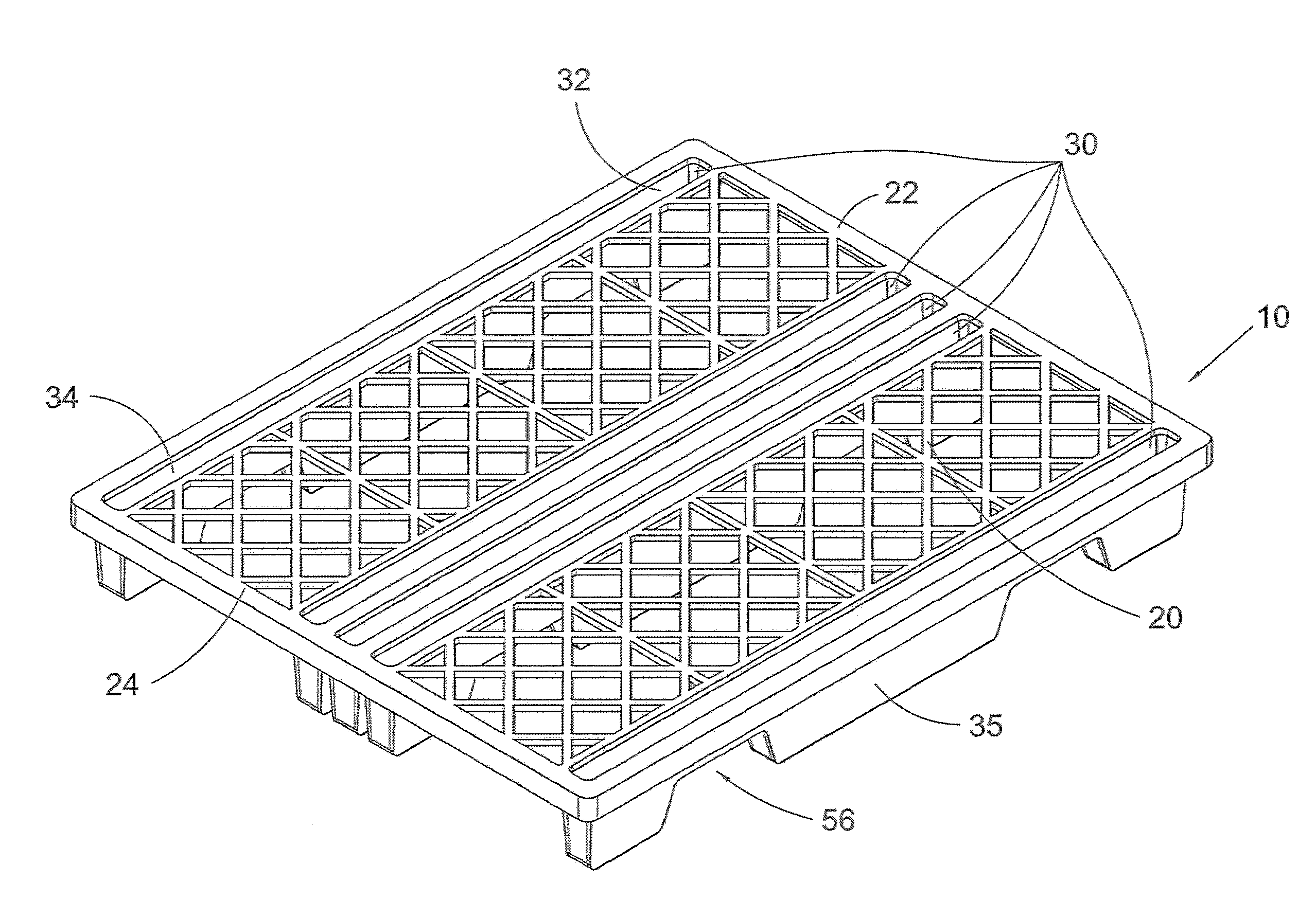
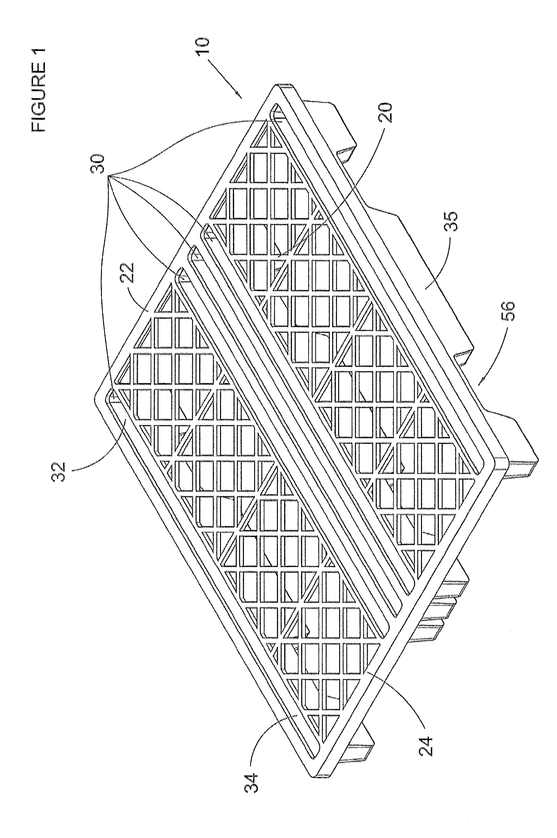
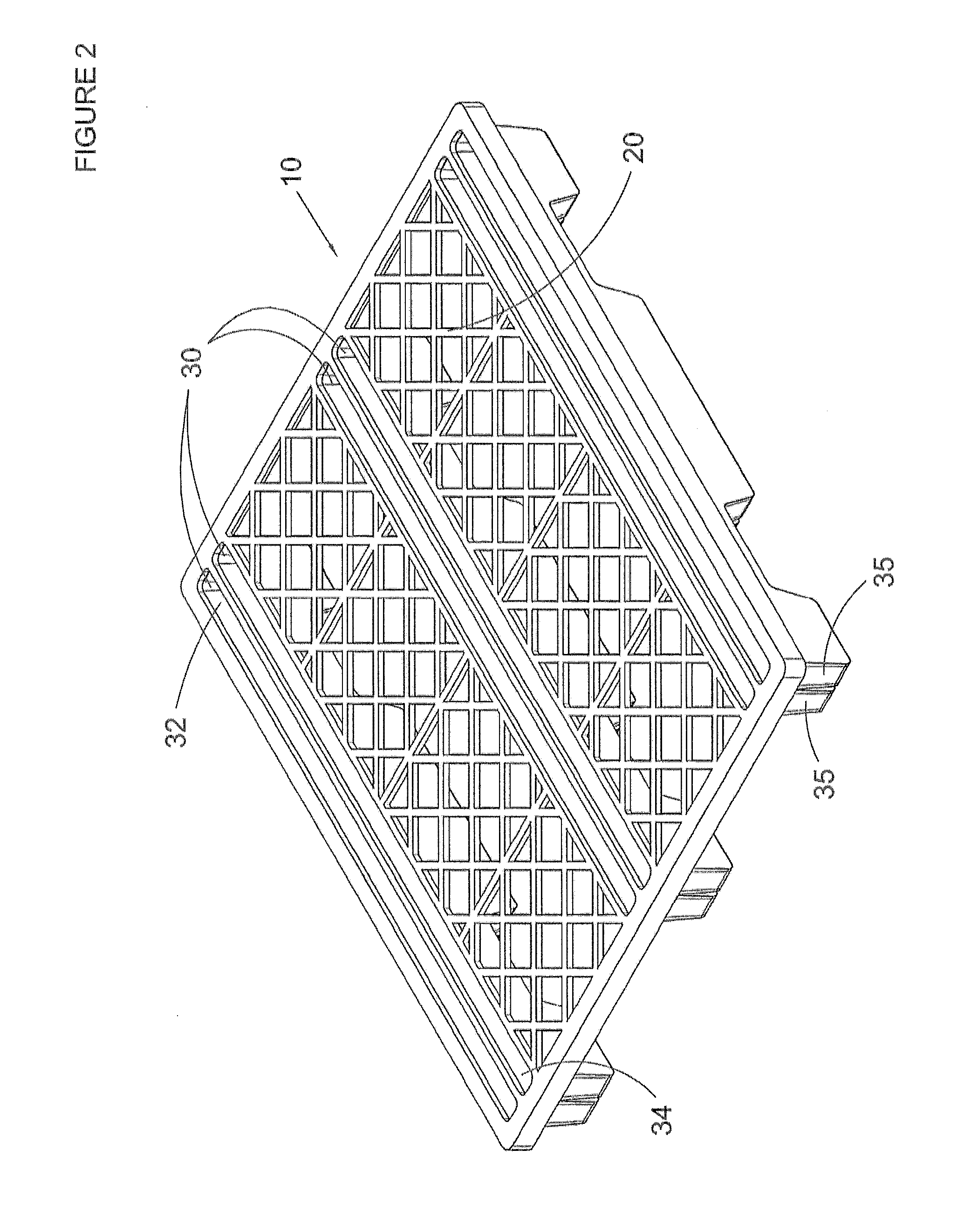
[0053]While not wishing to be limited to the following characteristics, one exemplary embodiment comprises a pallet made by a molding process which may be one of several types including but not limited to structural foam molding and injection molding using thermo plastic polymers, said pallet having overall dimensions of between about 48″ to about 36″ length, about 48″ to 36″ width, and a runner depth (from deck to V / U / flattened V bottom) of between about 2.5″ and about 8″. The runner opening into the deck is preferably between about 1″ to 4″ wide but may be wider or narrower depending on the desired load capacity of the pallet and the specific runner system design. It is possible to mold the pallet of single layer construction, or to employ rotational molding and create a pallet that is double-walled construction and / or hollow at least in part. The thickness of material can be selected to provide strength as needed for the pallet's intended use.

[0054]The pallet of the present inven...


PUM


Abstract

A pallet having a unique runner system where each runner opens into the upper deck of the pallet or opens away from the upper deck, and each runner is formed of a construction of z girts back to back resulting in a flattened “V” or “U”. Each runner may optionally include an elongated notch on its bottom surface or an opening to allow forklift tines to slide into for easy transport of the pallet. The pallet may also include cross runners of similar construction for additional strength. The pallet's construction allows the pallet to be made of plastic material, perhaps molded, providing lighter weight and longer durability than its wooden cousins.

Description

PRIORITY STATEMENT[0001]This application a nonprovisional application based off provisional application No. 61 / 865,012, which was filed on Aug. 12, 2013 with the U.S. Patent and Trademark Office, the entire contents of which is incorporated herein.BACKGROUND[0002]The transport of objects from one place to another has been a challenge since ancient times. Storage of multiple objects also poses challenges. In addition to specialized buildings, shelves, and cupboards for storage and bucket loaders, fork lifts, trucks, carts, planes and ships for transport, pallets have been created.[0003]Pallets can be thought of as a form of a moveable shelf or platform. Depending on the load to be moved, the construction of a pallet is critical to durability and performance. Further, it is desirable that a pallet be constructed such that a loaded pallet may be placed directly on the load of a pallet below without damaging the lower load. Some storage systems employ open racking of pallets which syste...

Claims


Application Information

Patent Timeline
Patent Type & Authority Applications(United States)
IPC IPC(8): B65D19/00
CPCB65D19/0048B65D2519/0094B65D2519/00069B65D2519/00034B65D2519/00955B65D19/0038B65D2519/00268B65D2519/00288B65D2519/00308B65D2519/00318B65D2519/00338
Inventor BURK, RYAN
Owner BURK RYAN
Learn More