
Field device

a field device and field technology, applied in the field of field devices, can solve the problems of increasing computing costs, affecting the performance of the keyboard,

Active Publication Date: 2015-02-05
VEGA GRIESHABER GMBH & CO
View PDF18 Cites 4 Cited by
  • Summary
  • Abstract
  • Description
  • Claims
  • Application Information

AI Technical Summary

Benefits of technology

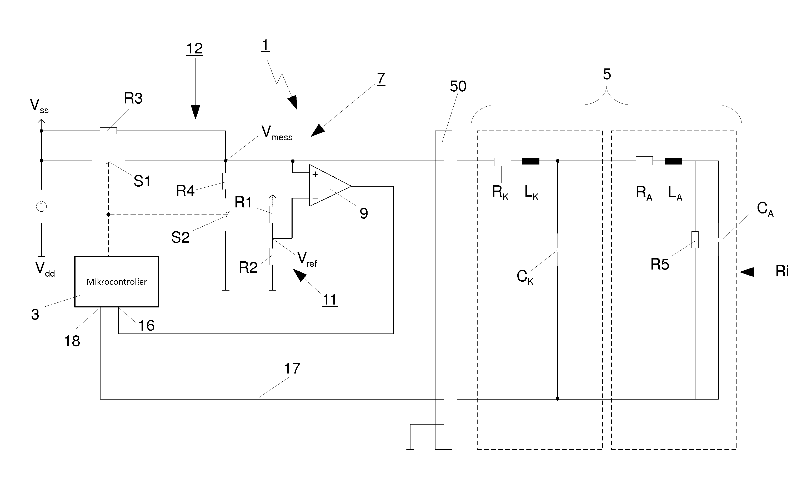
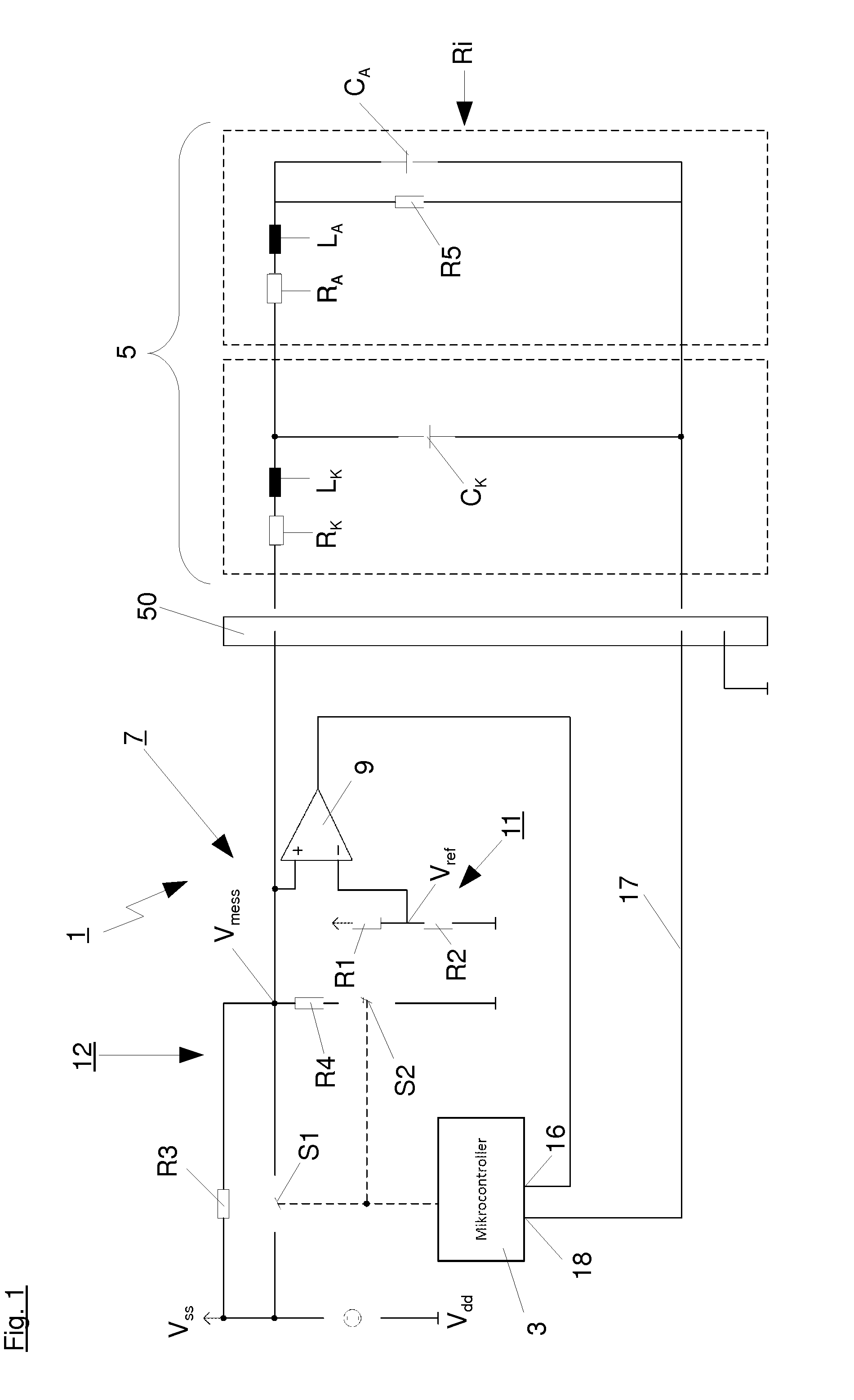
The patent describes a field device with a microprocessor and display that can be connected or disconnected from the field device. The microprocessor has an energy-saving mode where the display and operating module are switched off. A waking circuit detects when the display and operating module are disconnected and generates a waking signal. The device uses a voltage divider to generate a measuring voltage with very low power consumption, and the size of the resistances in the voltage divider are optimized to reduce power consumption. This design is simple and efficient, with a small size and low power consumption.

Problems solved by technology

By deactivating the interfaces and clocks of the processor, it no longer shows the original scope of functions as in the active mode so that certain functionalities, particularly in the field of data input and output, and thus, also during the operation of the display and / or operating modules, for example displays, LED's, or other output devices, as well as keyboards are considerably restricted or no longer possible at all.
However, such a polling results in increased computing expense and thus, power consumption and additionally, it prevents the energy saving modes of the microprocessor, in which an internal clock and / or interfaces of the microprocessor are deactivated.

Method used


Image

  • Field device
  • Field device

Examples


Embodiment Construction

[0028]The field device according to the invention comprises a microprocessor and a display and / or operating module that can be disconnected from said field device, with the microprocessor comprising an energy saving mode, in which the display and / or operating module are switched off, and being characterized in a waking circuit, generating a waking signal when the display and / or operating module is disconnected from the field device and is subsequently connected to it once more.

[0029]Such an embodiment achieves that the monitoring of the preferably shut-off display and / or operating module can occur based on the internal resistance at an interface to the field device and a change of the monitored resistance leads to the generation of a waking signal. Such monitoring can be realized in a particularly simple fashion when the waking switch shows a comparator. The comparator can perform a voltage monitoring, for example, with the comparator being fed with a reference voltage and a measuri...


PUM


Abstract

A field device with a microprocessor and a display and / or operating module, which can be disconnected from the field device, with the microprocessor showing an energy saving module, in which the display and / or operating module are switched off, with the waking circuit being provided, which generates a waking signal when the display and / or operating module are disconnected from the field device or connected thereto.

Description

CROSS REFERENCE TO RELATED APPLICATIONS[0001]This patent application claims priority European Patent Application 13 177 849.0, filed on Jul. 24, 2013.STATEMENT REGARDING FEDERALLY SPONSORED RESEARCH OR DEVELOPMENT[0002]No federal government funds were used in researching or developing this invention.NAMES OF PARTIES TO A JOINT RESEARCH AGREEMENT[0003]Not applicable.SEQUENCE LISTING INCLUDED AND INCORPORATED BY REFERENCE HEREIN[0004]Not applicable.BACKGROUND[0005]1. Field of the Invention[0006]The present invention relates to a field device.[0007]2. Background of the Invention[0008]The current state of knowledge is as follows.[0009]Such field devices are well known from prior art and comprise a microprocessor for controlling the field device and a display and / or operating module, which can be disconnected from the field device, with the display and / or operating module also being controlled by the microprocessor. The microprocessor here shows an energy saving mode, in which the displa...

Claims


Application Information

Patent Timeline
Patent Type & Authority Applications(United States)
IPC IPC(8): G06F1/32
CPCG06F1/3287G06F1/325G06F1/3265G05B19/0423G05B2219/13171G05B2219/23316G05B2219/25279G06F1/1654G06F1/3237G06F1/3278Y02D10/00Y02D30/50
Inventor ALLGAIER, VOLKERSTAIGER, HOLGER
Owner VEGA GRIESHABER GMBH & CO
Learn More