Projection exposure method and projection exposure apparatus for microlithography

a technology of projection exposure and microlithography, which is applied in the direction of microlithography exposure apparatus, printers, instruments, etc., can solve the problems of affecting the imaging performance, and affecting the image quality

Active Publication Date: 2015-01-29
CARL ZEISS SMT GMBH
View PDF4 Cites 7 Cited by
  • Summary
  • Abstract
  • Description
  • Claims
  • Application Information

AI Technical Summary

Benefits of technology

[0032]The adjustment or movement of a single manipulator can cause great alterations of position and / or form of the light quiver. Therefore, two or more manipulators turn often moved in a coordinated manner such that their effects on the generated image at least partly compensate for one another. In this case, too, taking account of changes to position and / or form of the light quiver can bring improved results.
[0034]The measurement surface can be a planar measurement surface or an at least regionally curved measurement surface, which can be spherically or aspherically curved. Measurement surface forms having high symmetry, for example planar or spherically curved measurement surfaces, can be advantageous with regard to simple evaluation of the intersection surface properties.
[0040]Preferably, at least two intersection surface properties are determined in temporal proximity or at the same time and the corresponding light quiver parameters thereof are taken into account computationally with one another or used for characterizing an intersection surface property. This makes it possible to obtain in many cases more reliable and / or better detailed information about the lighter quiver variation than in the case where only one light quiver parameter is determined. Moreover, if appropriate, it is possible to obtain additional information which cannot be obtained from each of the individual intersection surface properties by themselves. By way of example, a form change of the intersection surface can occur without the geometric centroid being displaced. Such form changes can then be distinguished from form changes with centroid displacement. As a result, e.g. statements about the symmetry of a form change are possible.

Problems solved by technology

Besides the intrinsic imaging aberrations which a projection lens can have on account of its optical design and production, imaging aberrations can also occur during the period of the use, e.g. during the operation of a projection exposure apparatus by the user.
Such imaging aberrations are often caused by alterations of the optical elements incorporated in the projection lens as a result of the projection radiation used in the course of the use.
Other internal or external disturbances can also lead to the impediment of the imaging performance.
They include, inter alia, a possible scale error of the mask, alterations of the air pressure in the surroundings, differences in the strength of the gravitational field between the location of the original lens adjustment and the location of use by the customer, changes in refractive index and / or form alterations of optical elements on account of material alterations as a result of high-energy radiation (e.g. compaction), deformations on account of relaxation processes in the holding devices, drifting of optical elements and the like.

Method used


Image

  • Projection exposure method and projection exposure apparatus for microlithography
  • Projection exposure method and projection exposure apparatus for microlithography
  • Projection exposure method and projection exposure apparatus for microlithography

Examples


Embodiment Construction

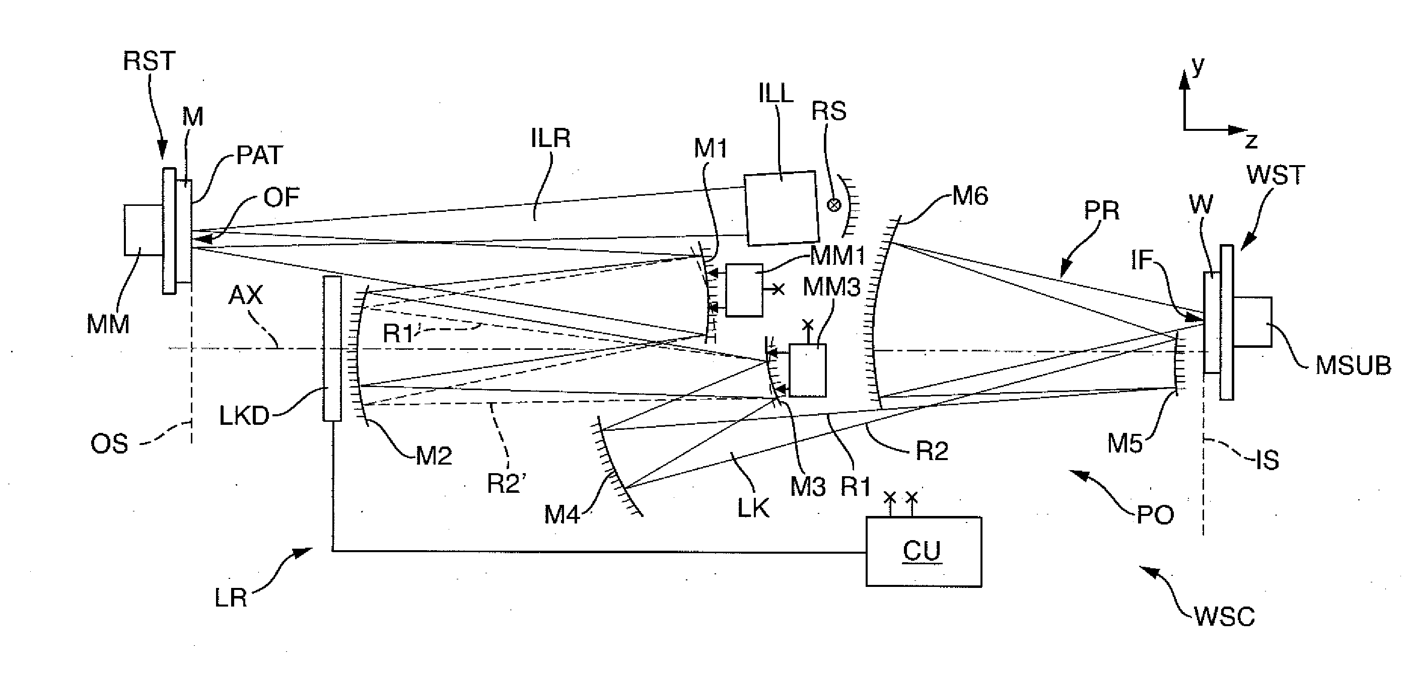
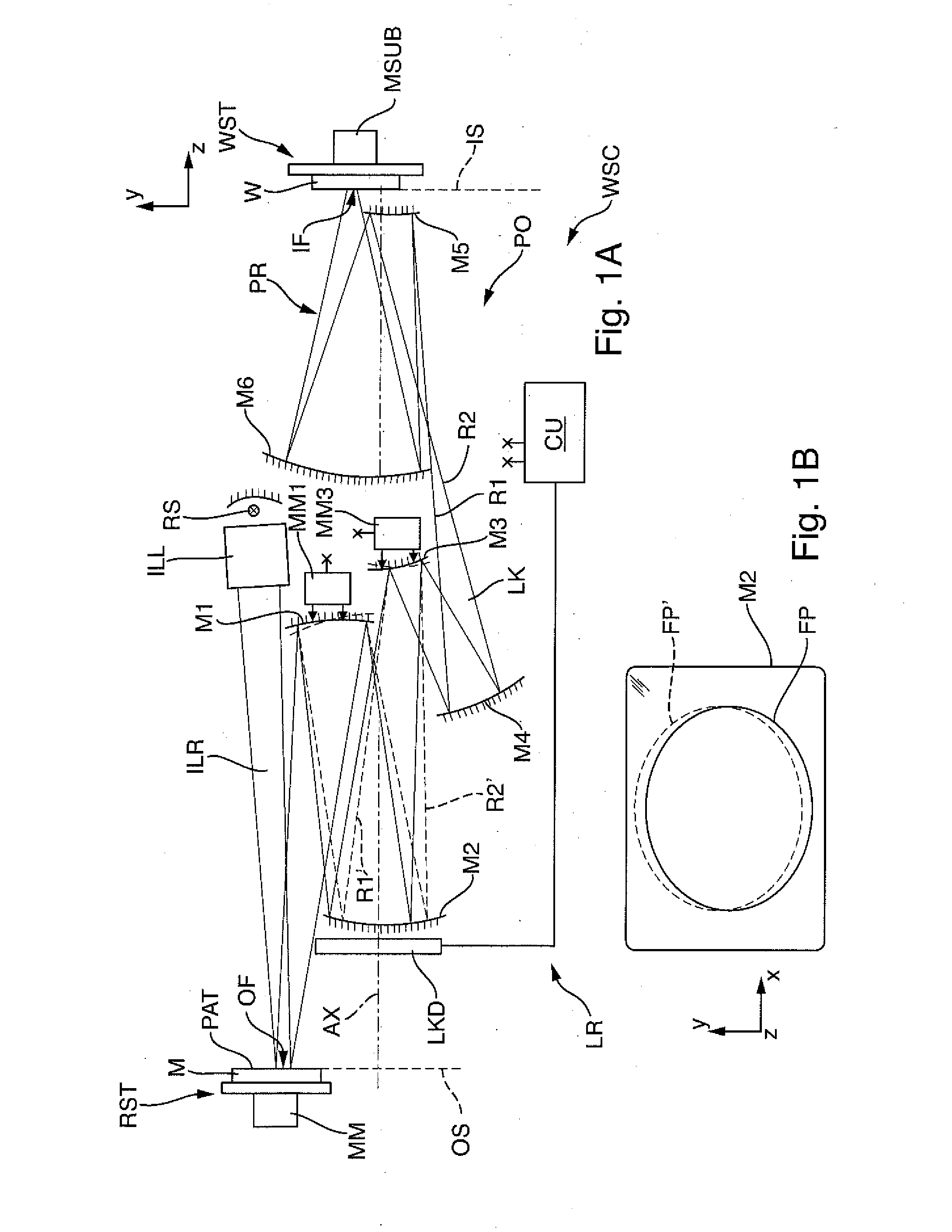
[0061]FIG. 1A schematically shows components of an EUV microlithography projection exposure apparatus WSC for exposing a radiation-sensitive substrate W arranged in the region of an image plane IS of a projection lens PO with at least one image of a pattern PAT of a reflective mask M, the pattern being arranged in the region of an object plane OS of the projection lens.

[0062]The projection exposure apparatus is operated with the radiation of a primary radiation source RS. An illumination system ILL serves for receiving the radiation of the primary radiation source and for shaping illumination radiation ILR directed onto the pattern. The projection lens PO serves for imaging the structure of the pattern onto the light-sensitive substrate W.

[0063]The primary radiation source RS can be, inter alia, a laser plasma source or a gas discharge source or a synchrotron-based radiation source. Such radiation sources generate a radiation in the extreme ultraviolet range (EUV range), in particul...


PUM

PropertyMeasurementUnit
operating wavelengthsaaaaaaaaaa
wavelengthsaaaaaaaaaa

Abstract

A projection exposure method for exposing a radiation-sensitive substrate with at least one image of a pattern of a mask is provided. The method includes determining at least one light quiver parameter which describes a property of a light quiver, and controlling the operation of the projection exposure apparatus taking account of the light quiver parameter.

Description

CROSS-REFERENCE TO RELATED APPLICATIONS[0001]The present application is a continuation of, and claims benefit under 35 USC 120 to, international application PCT / EP2013 / 052963, filed Feb. 14, 2013, which claims benefit under 35 USC 119 of German Application No. 10 2012 202 536.7, filed Feb. 20, 2012. International application PCT / EP2013 / 052963 also claims priority under 35 USC 119(e) to U.S. Provisional Application No. 61 / 601,126, filed Feb. 21, 2012. The entire disclosures of international application PCT / EP2013 / 052963 and German Application No. 10 2012 202 536.7 are incorporated by reference herein.BACKGROUND[0002]1. Field of the Invention[0003]The invention relates to a projection exposure method for exposing a radiation-sensitive substrate with at least one image of a pattern of a mask, and to a projection exposure apparatus suitable for carrying out the method.[0004]2. Description of the Prior Art[0005]Microlithographic projection exposure methods are predominantly used nowadays...

Claims


Application Information

Patent Timeline
Patent Type & Authority Applications(United States)
IPC IPC(8): G03F7/20
CPCG03F7/70133G03F7/70258G03F7/7085
Inventor GRAESCHUS, VOLKERGRUNER, TORALF
Owner CARL ZEISS SMT GMBH
Why Eureka
Try Eureka