
Parking caliper assembly

a technology for parking calipers and assembly parts, which is applied in the direction of friction lining, braking discs, braking systems, etc., can solve the problems of reducing the overall dimensions of the parking caliper assembly, and the solution is particularly bulky

Active Publication Date: 2015-01-29
FRENI BREMBO SPA
View PDF18 Cites 28 Cited by
  • Summary
  • Abstract
  • Description
  • Claims
  • Application Information

AI Technical Summary

Benefits of technology

The invention relates to a brake caliper assembly for vehicles. The invention solves the issue of interference between the brake pads and the caliper body during braking, and ensures accurate and reliable operation of the assembly over a wide range of conditions. The solution involves suspending the brake pad from a suspension pin on the caliper body and moving it away from the brake disc, while still allowing it to slide against the caliper body. The invention is compact and can withstand high levels of pollution and dust, making it ideal for use in various environmental conditions. Overall, the invention provides a reliable and safe brake caliper assembly that meets the requirements of high-performance vehicles.

Problems solved by technology

Such a solution is particularly bulky, especially in the circumferential direction.
In this case also, this solution is particularly bulky, since it requires the provision of a bracket projecting towards the disc to provide an abutment surface laterally to the pad.
Other solutions are known by U.S. Pat. No. 3,841,444 A, JP 55 152931 A, DE 10 2005 044150 A1, U.S. Pat. No. 3,976,167 A, GB 2 060 093 A. However, none of these solutions allows reducing the overall dimensions of the parking caliper assembly, housing, supporting, and guiding a pad for disc brakes.

Method used


Image

  • Parking caliper assembly
  • Parking caliper assembly
  • Parking caliper assembly

Examples


Embodiment Construction

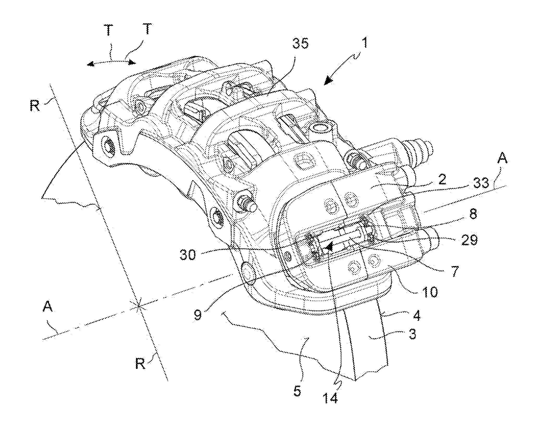
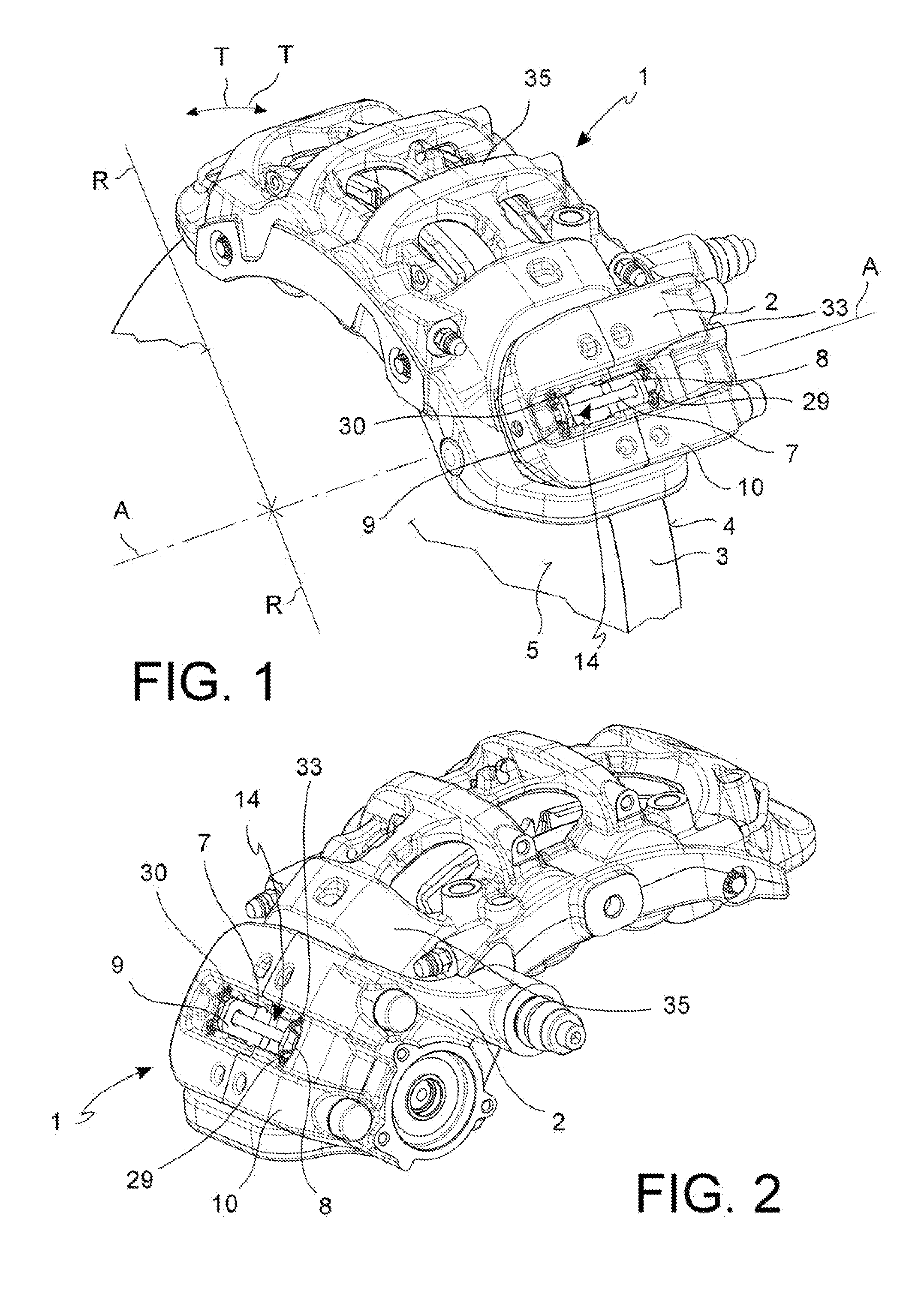
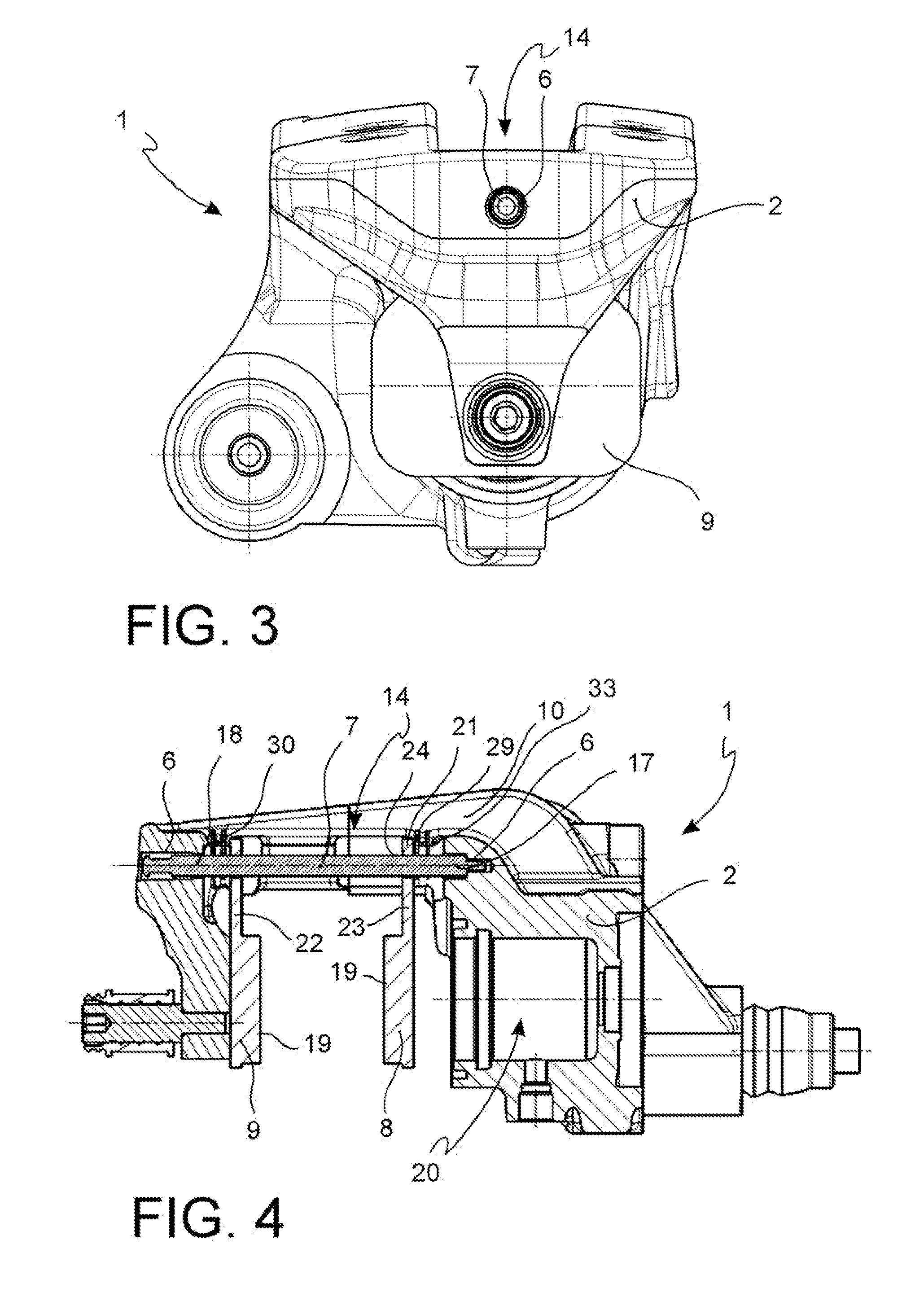
[0070]With reference to the above-mentioned figure, a caliper assembly for parking disc brake 1 comprises a parking caliper body 2 arranged astride of a disc for disc brake 3 so as to exert, on at least one braking surface 4; 5 thereof, a braking action capable of holding a vehicle in a parking position.

[0071]In accordance with an embodiment, said disc 3 has a substantially asymmetric body suitable to rotate about a rotational axis defining an axial direction to the disc A-A, a direction orthogonal to this axial direction or radial direction to the disc R-R, and a direction orthogonal to said axial direction and said radial direction or tangential direction to the disc T-T, or circumferential direction.

[0072]In accordance with an embodiment, said caliper body 2 comprises a pin seat 6 suitable to receive a suspension pin 7 of at least one pad for disc brake 8; 9.

[0073]In accordance with an embodiment, an upper surface of the caliper body 33 faces the side opposite to the braking disc...


PUM


Abstract

An assembly comprising a caliper body (2) of a caliper assembly for parking disc brake, said caliper body (2) comprising a channel (14), said axial channel (14) being defined by at least one wall having at least one flattened length forming at least one guide surface (15; 16); at least one portion of caliper body (10) projecting towards the disc or above the disc (3), said portion of caliper body (10) comprising a surface facing the disc (11) or at least the friction material (12) of said pad (8), and wherein said surface facing the disc (11) has a flattened length forming at least one abutment surface (12; 13) and wherein said at least one guide surface (15; 16) is oriented differently with respect to said at least one abutment surface (12; 13) so as to avoid that they are mutually coplanar; said guide surface (15; 16) is suitable to face an opposite guide surface (25; 26) provided for on an associable supporting plate (21, 22) of an associable pad (8) in order to allow the positioning and sliding thereof against the caliper body (2) and wherein, in said abutment surface (12, 13), it is suitable to face an opposite abutment surface (27, 28) provided for on the supporting plate (21, 22) of at least one associable pad (8) so as to allow the pad to abut and slide against said abutment surface (12; 13).

Description

FIELD OF THE INVENTION[0001]The present invention relates to a parking caliper assembly.[0002]In particular, the present invention relates to a parking caliper body to which a, suspension pin for pads and at least one pad suspended to said pin are associated, as well as a suspension spring acting between said pin and said caliper body.BACKGROUND OF THE PRIOR ART[0003]The document U.S. Pat. No. 5,323,882 by Waterman George H. discloses a pad for brake disc supporting to the caliper body by overhangs of the supporting plate of the friction material arranged laterally to the friction material and received in apposite seats provided for in the caliper body. This embodiment is aimed to the implementation of a caliper body projecting towards the braking disc so as to form abutment surfaces arranged on the pad sides. Such a solution is particularly bulky, especially in the circumferential direction.[0004]The document DE 38 39 477 by Alfred Teves GmbH shows a pad having a supporting plate p...

Claims


Application Information

Patent Timeline
IPC IPC(8): F16D65/00F16D65/092B60T1/06F16D65/12
CPCF16D65/0075B60T1/065F16D65/092F16D65/12F16D55/224F16D65/0973F16D65/0975F16D2055/0041F16D2055/007
Inventor NESSI, LORENZOBONETTI, ADRIANOCRIPPA, CRISTIAN
Owner FRENI BREMBO SPA
Learn More