
Firearm Lead Sight

a lead sight and firearm technology, applied in the field of firearm accessories, can solve the problems and is often faced with the difficult task of shooting and hitting a moving targ

Active Publication Date: 2015-01-29
FREDERICK AARON WADE
View PDF18 Cites 5 Cited by
  • Summary
  • Abstract
  • Description
  • Claims
  • Application Information

AI Technical Summary

Benefits of technology

The invention allows a shooter to aim at a moving target in both right and left directions. The shooteer can use the appropriate sight for the direction of the movement. This ensures that the firearm barrel is oriented at the proper distance in advance of the moving target as the shot is fired.

Problems solved by technology

When operating a firearm, a shooter is often faced with the difficult task of shooting and hitting a moving target.

Method used


Image

  • Firearm Lead Sight
  • Firearm Lead Sight
  • Firearm Lead Sight

Examples


Embodiment Construction

[0015]All illustrations of the drawings are for the purpose of describing selected versions of the present invention and are not intended to limit the scope of the present invention.

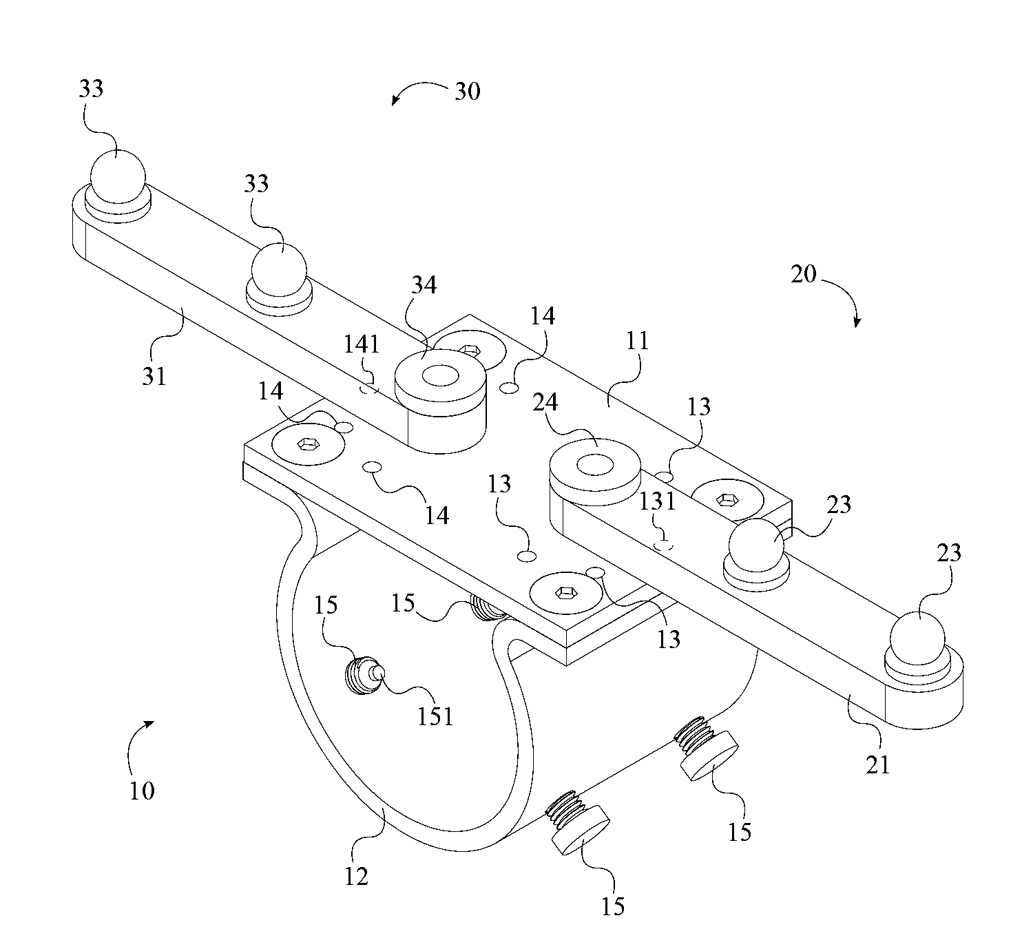
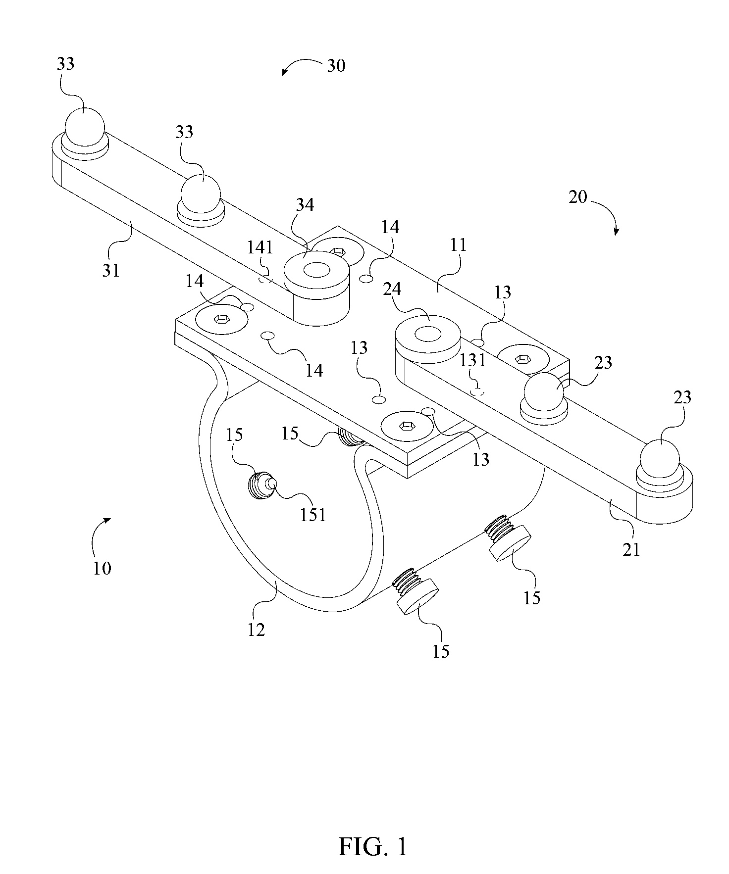
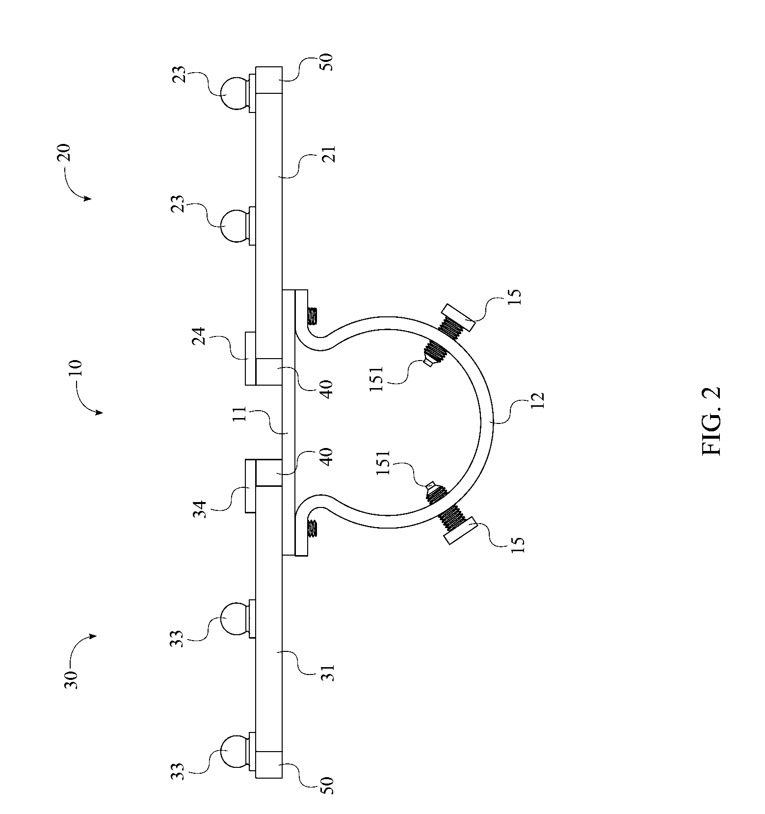
[0016]The present invention is a firearm lead sight that assists a shooter in shooting a moving target. The present invention is retro fit attachment for firearms and can be designed to be integrated with any type of firearm. The firearm lead sight comprises a mount 10, a first sight assembly 20, and a second assembly. The mount 10 provides a means for attaching the present invention to the barrel of a firearm and supports both the first sight assembly 20 and the second sight assembly 30. The first sight assembly 20 and the second sight assembly 30 provide indicators for leading a moving target while shooting.

[0017]In reference to FIG. 1, the mount 10 comprises a mount plate 11, a barrel grip 12, a plurality of first notches 13, and a plurality of second notches 14. The barrel grip 12 is adjacently attac...


PUM


Abstract

A firearm lead sight that is attached to the barrel of a firearm for assisting a shooter in leading a moving target. The firearm lead sight includes a mount, a first sight assembly, and a second sight assembly. A mount plate and a barrel grip form the mount and are clamped around the barrel of the firearm. A first sight bar and a second sight bar, of the first sight assembly and the second sight assembly respectively, are pivotally connected to the mount plate opposite each other. A first plurality of sight marks is positioned along the first sight bar, while a second plurality of sight marks is positioned along the second sight bar. A first detent of the first sight bar and a second detent of the second sight bar allow the first sight bar and the second sight bar to be locked in a variety of positions.

Description

[0001]The current application claims a priority to the U.S. Provisional Patent application Ser. No. 61 / 858,697 filed on Jul. 26, 2013.FIELD OF THE INVENTION[0002]The present invention relates generally to firearm accessories and more particularly, firearm sights. More specifically, the present invention is an attachable, deployable, and adjustable firearm lead sight with multiple sight beads that allow a shooter to compensate for target movement.BACKGROUND OF THE INVENTION[0003]When operating a firearm, a shooter is often faced with the difficult task of shooting and hitting a moving target. This is commonly encountered in hunting as hunters must quickly shoot moving animals such as deer and birds before the animals are able to escape or get out of range. There are typically two techniques that shooters may use when shooting a moving target. The first technique is generally referred to as “leading” or “tracking” and involves following the movement of the target. After the shooter ha...

Claims


Application Information

Patent Timeline
IPC IPC(8): F41G1/033
CPCF41G1/033F41G11/004F41G1/473
Inventor FREDERICK, AARON WADE
Owner FREDERICK AARON WADE
Learn More