Heart therapy device for detecting ventricular tachycardia and fibrillation

Active Publication Date: 2015-01-22
BIOTRONIK SE & CO KG
View PDF2 Cites 0 Cited by
  • Summary
  • Abstract
  • Description
  • Claims
  • Application Information

AI Technical Summary

Benefits of technology

The heart therapy device described in this patent ensures that patients with ventricular tachycardia receive effective treatment, even if different types of tachycardia occur in both ventricles. It prevents incorrect detections caused by dislocated electrodes and avoids the risk of atrial fibrillation. This treatment device can provide a safer and more effective therapy for patients with ventricular tachycardia.

Problems solved by technology

Based on the observation that there are ventricular tachycardias that have a considerable frequency difference between the right and left ventricle over a considerable period of time, typically, in the event of just right-ventricular detection, there is a potential risk that patients having these dysrhythmias are not being cared for sufficiently.
For example, with a much quicker VT / VF in the left ventricle with a moderate VT in the right ventricle, generally, there is a risk of a lethal appearance of the dysrhythmia, since the time it takes for effective defibrillation is considerably too long as a result of the underestimation only using right-ventricular sensing.
Typically, purely biventricular sensing poses a risk that, for example in the event of a left-ventricular electrode (coronary sinus electrode) dislocated in the region of the atrium, an atrial fibrillation is incorrectly classified as left-ventricular fibrillation (left-VF) and thus leads to an inadequate therapy delivery.
Known biventricular heart therapy devices are generally inadequate with respect to dissimilar ventricular tachycardias.

Method used


Image

  • Heart therapy device for detecting ventricular tachycardia and fibrillation
  • Heart therapy device for detecting ventricular tachycardia and fibrillation
  • Heart therapy device for detecting ventricular tachycardia and fibrillation

Examples


Embodiment Construction

[0043]The following description is of the best mode presently contemplated for carrying out at least one embodiment of the invention. This description is not to be taken in a limiting sense, but is made merely for the purpose of describing the general principles of the invention. The scope of the invention should be determined with reference to the claims.

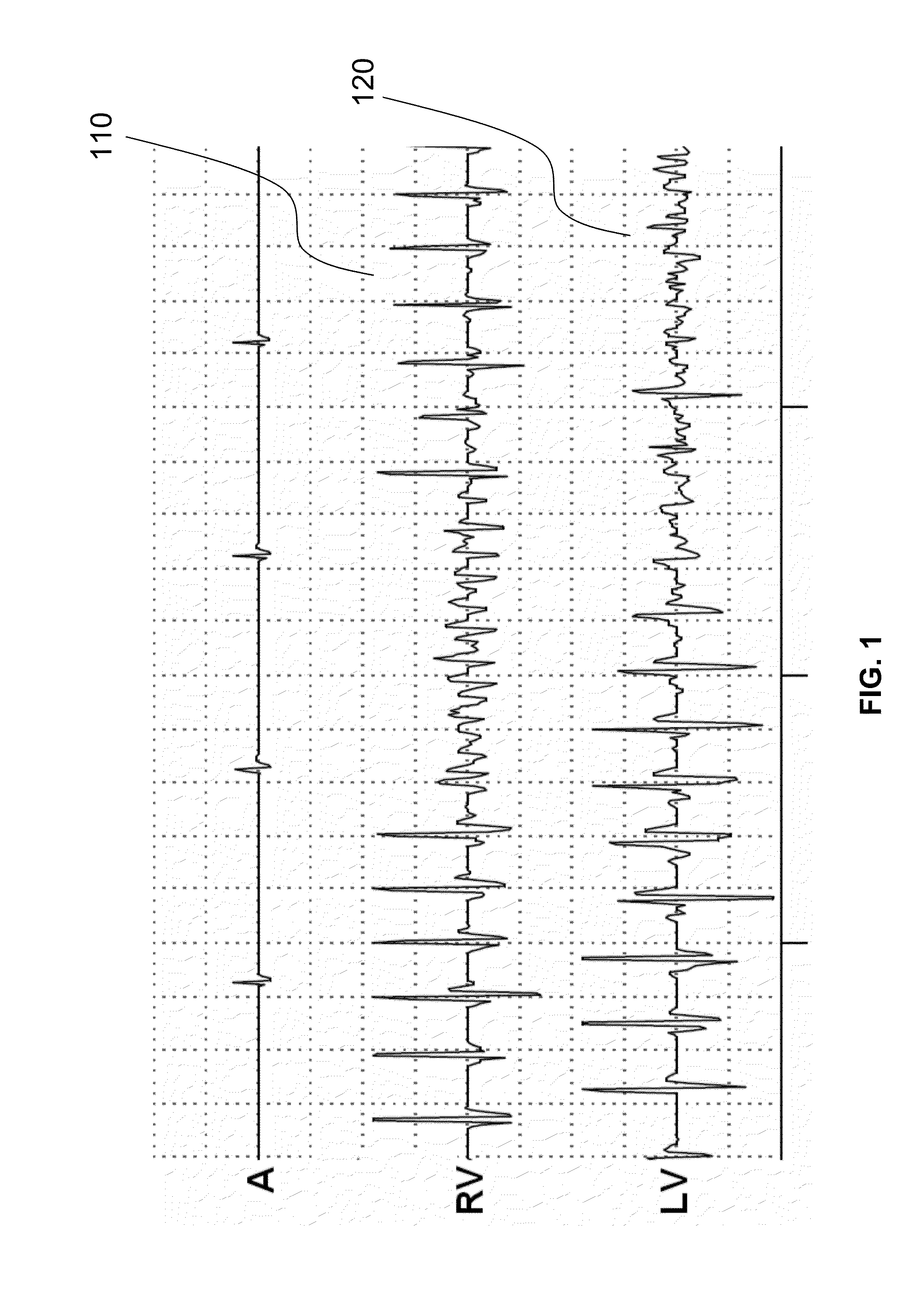
[0044]FIG. 1 shows an example of a dissimilar ventricular tachyarrhythmia. As shown in FIG. 1, the rhythm changes in the right ventricle (RV) from a stable VT over a short phase of VF to a slower VT 110, and at the same time the rhythm in the LV channel changes at a later moment in time from a stable VT to a lasting VF, which is not sensed with a purely right-ventricular detection and may lead to an incorrect choice of therapy.

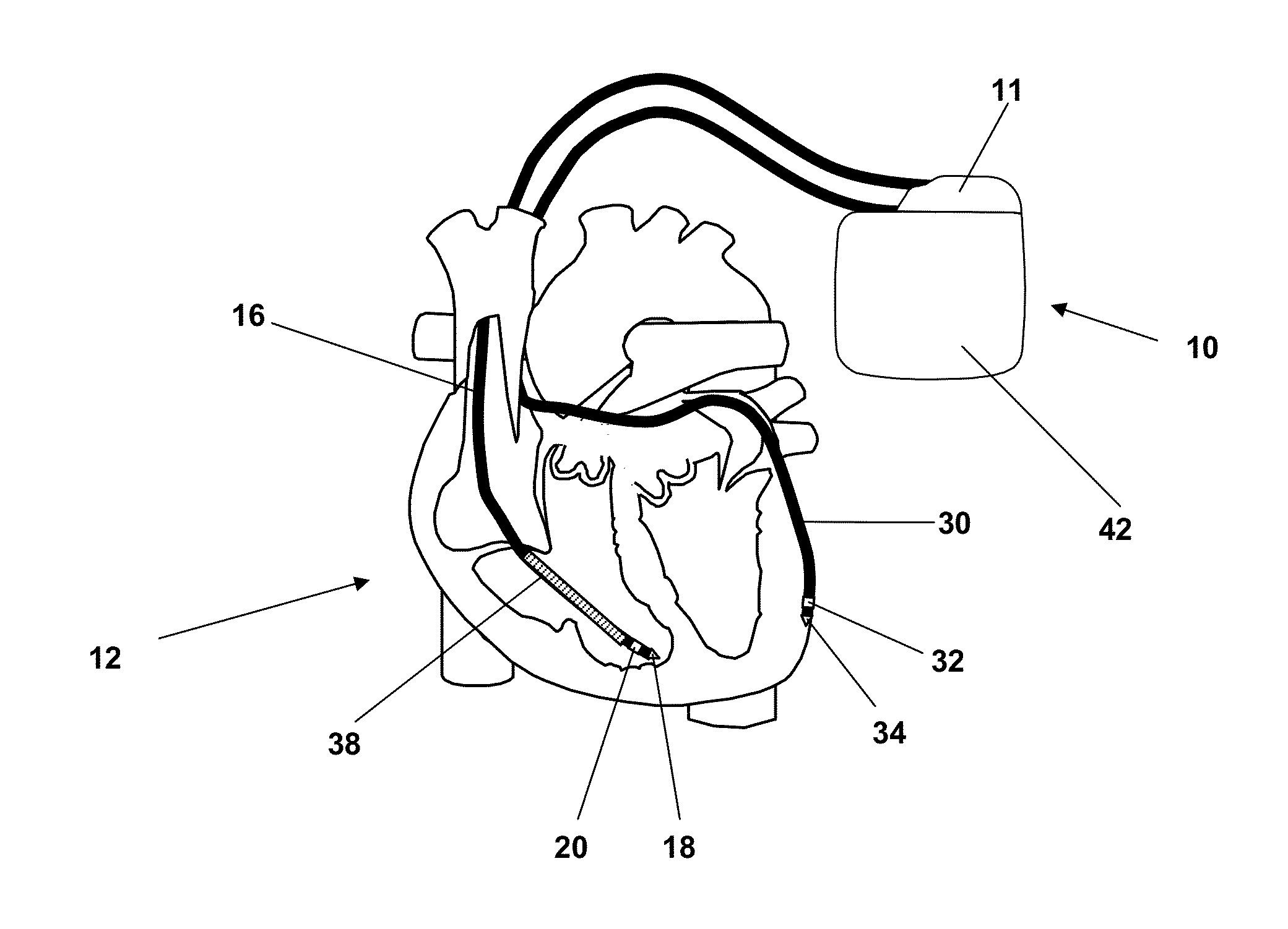
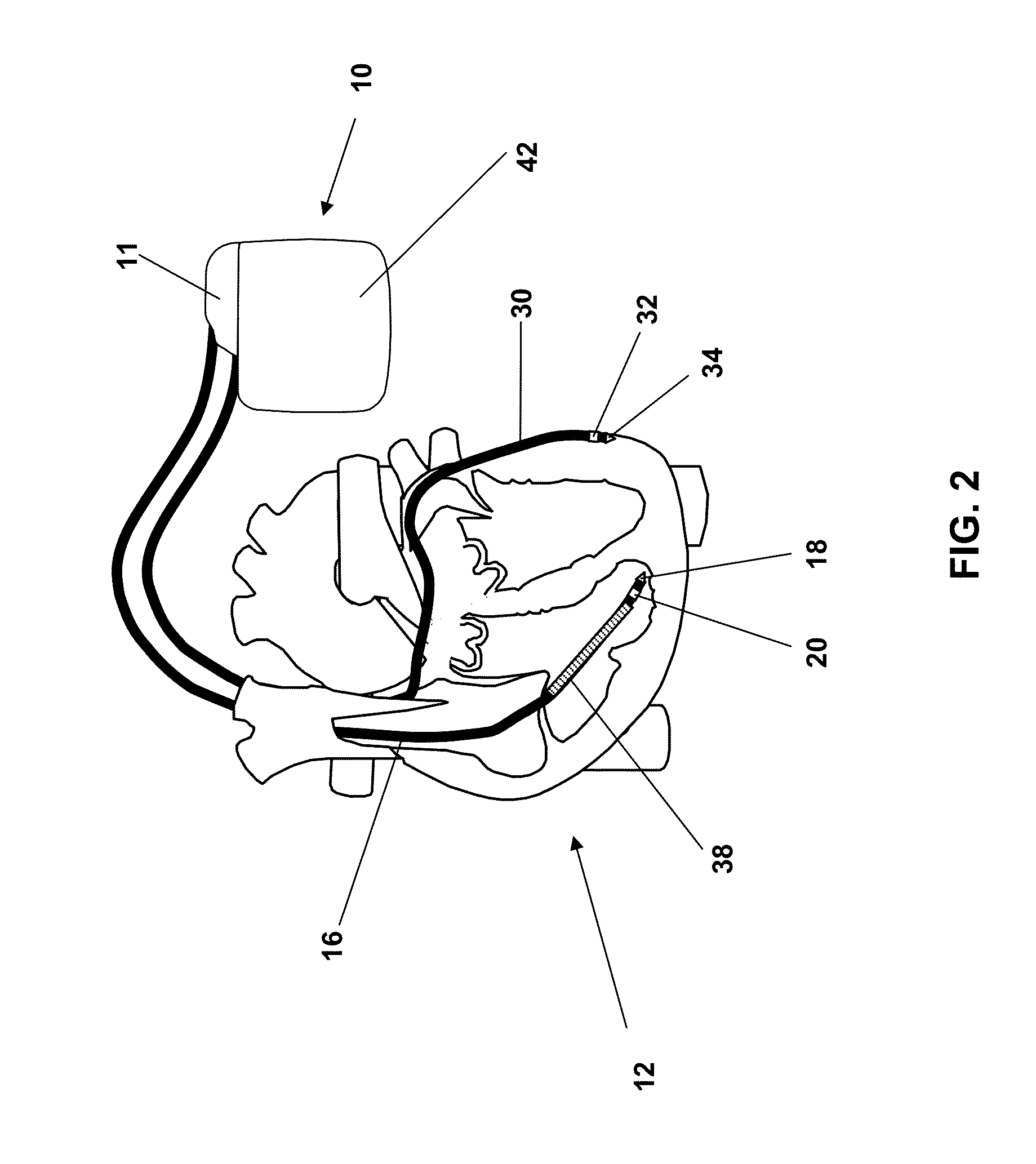
[0045]FIG. 2 shows a biventricular cardiac pacemaker-defibrillator (ICD or CRT-D), having a right-ventricular defibrillation shock coil, as an implantable cardiac stimulation such as an implantable heart ther...


PUM


Abstract

A heart therapy device having a right-ventricular electrode and a left-ventricular electrode connected to a tachycardia identification unit. The tachycardia identification unit identifies ventricular tachycardia and simultaneously evaluates the heart rate at the right-ventricular and left-ventricular electrodes. The ventricular electrodes each include an electrode line having a corresponding sensing electrode pole that senses electric potential courses in the myocardium of the respective ventricle. The heart therapy device includes a dislocation identification unit that detects a possible dislocation of one of the ventricular electrodes, simultaneously evaluates the heart rate at both ventricular electrodes, and signals a right-ventricular or left-ventricular dislocation when a sudden rise in heart rate is sensed at the right-ventricular or left-ventricular electrode, without detecting a considerable change in rhythm at the respective electrode. In the event of the dislocation of one of the ventricular electrodes, the rhythm information of the electrode in question is ignored for tachycardia detection.

Description

[0001]This application claims the benefit of U.S. Provisional Patent Application 61 / 847,093, filed on 17 Jul. 2013, and U.S. Provisional Patent Application 61 / 865,625, filed on 14 Aug. 2013, the specifications of which are hereby incorporated herein by reference.BACKGROUND OF THE INVENTION[0002]1. Field of the Invention[0003]Embodiments of the invention generally relate to implantable biventricular heart therapy devices that detect ventricular tachycardia and fibrillation.[0004]2. Description of the Related Art[0005]Typically, tachycardia identification units allow biventricular detection of tachyarrhythmias, such as ventricular tachycardias (VT) or fibrillations (VF). Generally, therapy device control may initiate suitable therapies based on the detection.[0006]A system known as an S-ICD system typically operates with a far-field channel for VT / VF identification.[0007]For example, a specific type of tachyarrhythmias is “dissimilar” ventricular tachycardias, in which different (beat...

Claims


Application Information

Patent Timeline
IPC IPC(8): A61N1/39
CPCA61N1/3987A61N1/3684A61N1/3962A61N1/3622A61N1/36592A61N1/37A61N1/36843A61N1/39622
Inventor KUCHER, ANDREASDOERR, THOMAS
Owner BIOTRONIK SE & CO KG
Why Eureka
Try Eureka