
Shroud block segment for a gas turbine

a technology of shroud block and gas turbine, which is applied in the manufacture of engines, machines/engines, mechanical equipment, etc., can solve the problems of reducing the overall efficiency of the turbine, and the cooling provided to and the modification or tuning of the shroud block segment becomes limited

Active Publication Date: 2015-01-08
GENERAL ELECTRIC CO
View PDF11 Cites 42 Cited by
  • Summary
  • Abstract
  • Description
  • Claims
  • Application Information

AI Technical Summary

Benefits of technology

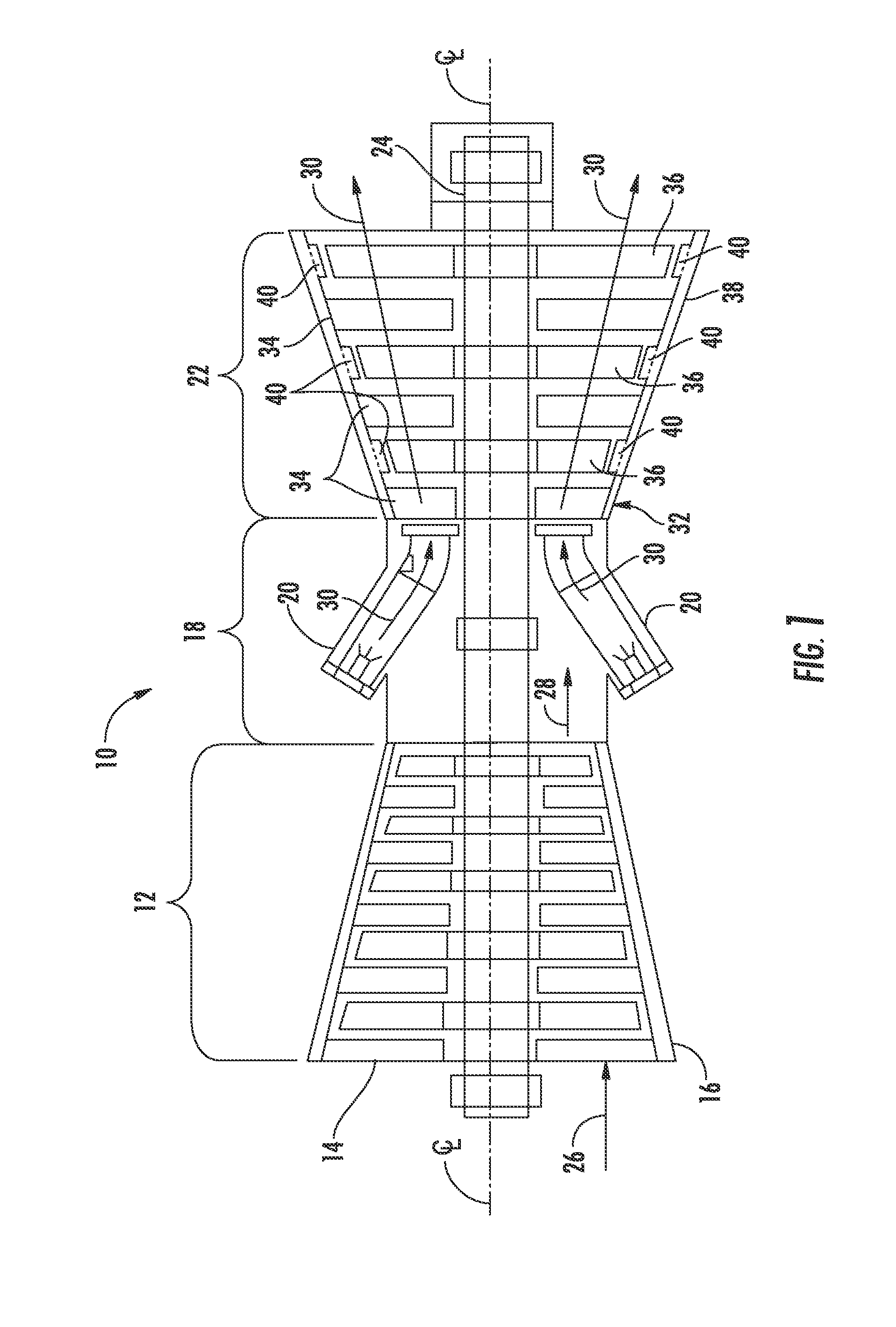
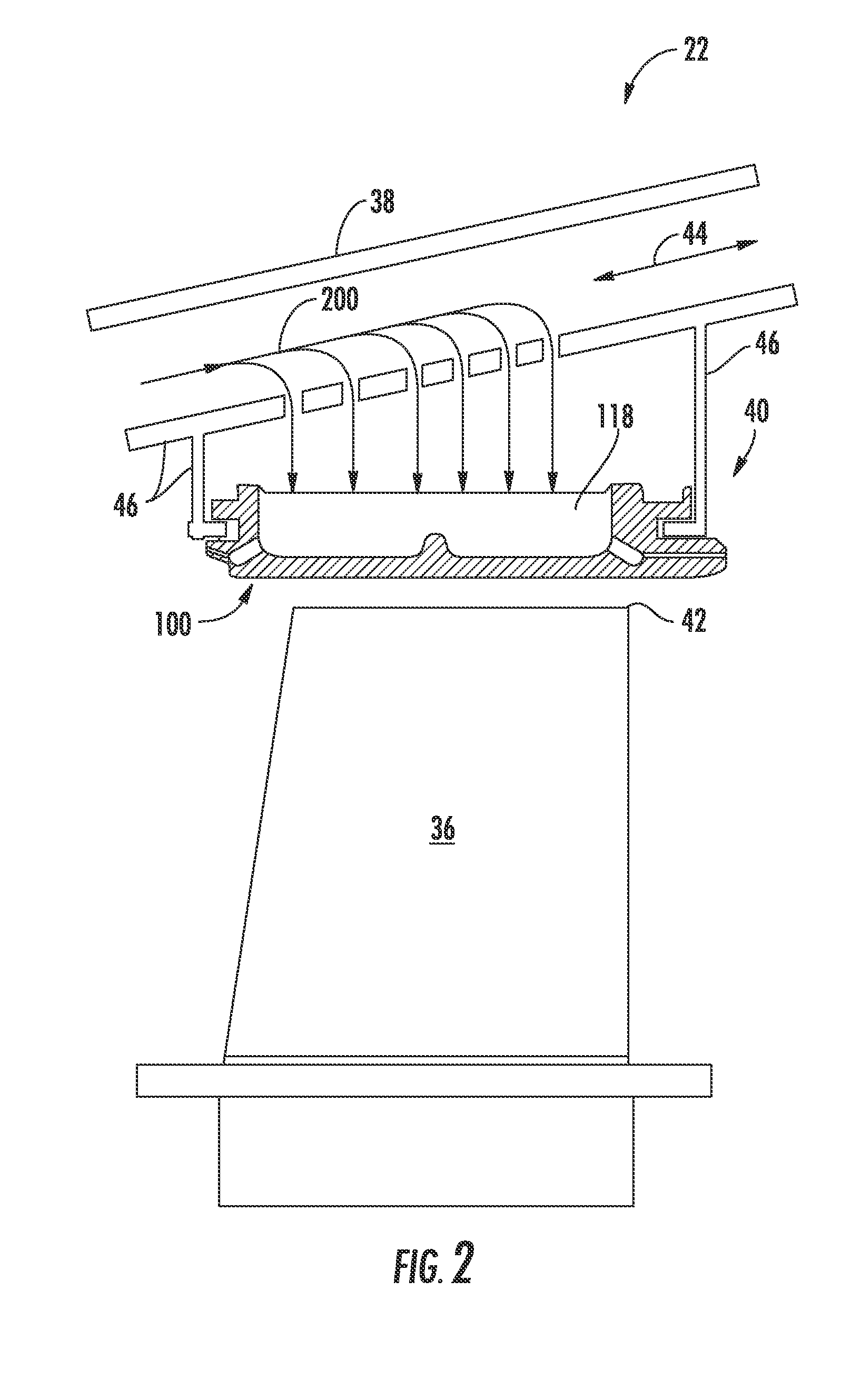
The present invention is a new design for a shroud block segment in a gas turbine. The segment includes a main body with an arcuate combustion gas side and a cooling chamber defined in the back side. A cooling plenum and an exhaust passage are defined within the main body to provide fluid communication out of the cooling plenum. An insert opening extends within the main body through the back side towards the cooling plenum, and a cooling flow insert or a cooling flow impingement plate is disposed within the insert opening to provide fluid communication between the cooling chamber and the cooling plenum. The design also includes a cooling flow passages that provide fluid communication between the cooling chamber and the cooling plenum. The technical effects of the invention include improved cooling performance, reduced cooling flow rate, and improved cooling flow direction.

Problems solved by technology

Leakage of the combustion gases over the blade tips generally results in a decrease in overall turbine efficiency.
Once the cooling passages have been cast and / or machined into the shroud block segment the ability to later modify the size, pattern and quantity of the cooling passages thereby modifying or tuning the cooling provided to the shroud block segment becomes limited.

Method used


Image

  • Shroud block segment for a gas turbine
  • Shroud block segment for a gas turbine
  • Shroud block segment for a gas turbine

Examples


Embodiment Construction

[0027]Reference will now be made in detail to present embodiments of the invention, one or more examples of which are illustrated in the accompanying drawings. The detailed description uses numerical and letter designations to refer to features in the drawings. Like or similar designations in the drawings and description have been used to refer to like or similar parts of the invention. As used herein, the terms “first”, “second”, and “third” may be used interchangeably to distinguish one component from another and are not intended to signify location or importance of the individual components. The terms “upstream” and “downstream” refer to the relative direction with respect to fluid flow in a fluid pathway. For example, “upstream” refers to the direction from which the fluid flows, and “downstream” refers to the direction to which the fluid flows. The term “radially” refers to the relative direction that is substantially perpendicular to an axial centerline of a particular compone...


PUM


Abstract

A shroud block segment for a gas turbine includes a main body having a leading portion, a trailing portion, a first side portion and an opposing second side portion that extend axially between the leading portion and the trailing portion. The main body further includes an arcuate combustion gas side, an opposing back side and a cooling chamber defined in the back side. A cooling plenum and an exhaust passage are defined within the main body where the exhaust passage provides for fluid communication out of the cooling plenum. An insert opening extends within the main body through the back side towards the cooling plenum. A cooling flow insert is disposed within the insert opening. The cooling flow insert comprises a plurality of cooling flow passages that provide for fluid communication between the cooling chamber and the cooling plenum.

Description

FIELD OF THE INVENTION[0001]The present invention generally involves a gas turbine. More specifically, the invention relates to cooling of a shroud block segment within a turbine section of the gas turbine.BACKGROUND OF THE INVENTION[0002]A gas turbine generally includes a compressor, a combustor disposed downstream form the compressor and a turbine section disposed downstream from the combustor. A working fluid such as air enters the compressor where it is progressively compressed to provide a compressed working fluid to the combustor. Fuel is mixed with the compressed working fluid within the combustor and the mixture it is burned to produce combustion gases at a high temperature and a high velocity. The combustion gases are then routed from the combustor into the turbine section where thermal and / or kinetic energy are extracted to produce work.[0003]The turbine section generally includes a plurality of rotor blades that extend radially from a rotor disk that is coupled to a rotor...

Claims


Application Information

Patent Timeline
IPC IPC(8): F01D25/12
CPCF01D25/12F01D11/24F05D2240/11F05D2250/191F05D2260/201F05D2260/205
Inventor SEZER, IBRAHIMSINGH, ANSHUMANITZEL, GARY MICHAELVEHR, JAMES WILLIAM
Owner GENERAL ELECTRIC CO
Learn More