
High strength ceramic fibers and methods of fabrication

Active Publication Date: 2015-01-01
FREE FORM FIBERS LLC
View PDF4 Cites 37 Cited by
  • Summary
  • Abstract
  • Description
  • Claims
  • Application Information

AI Technical Summary

Benefits of technology

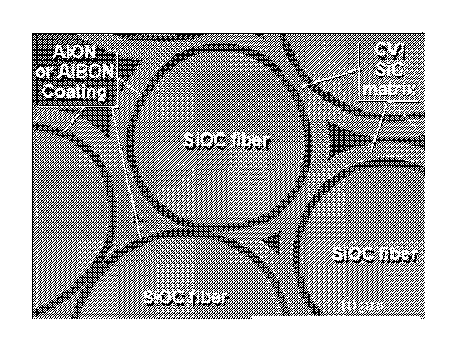
The present invention provides a fiber structure and method for forming an interphase in a ceramic matrix composite material having a plurality of SiC fibers. The fiber structure includes a plurality of fibers arranged in a structure with a matrix between them and a multilayer coating along the surfaces of at least some of the fibers. This multilayer coating includes an inner layer region with sheet-like strength and an outer layer region with particle-like strength, which prevents the cracks from approaching the fibers. The method includes selectively removing silicon out of the surface of the fibers to create a porous carbon layer on the fibers, and then replacing the carbon layer with an interphase layer which coats the fibers to minimize fiber-to-fiber bridging in the preform. Overall, this invention improves the toughness and strength of the fiber structure.

Problems solved by technology

Yet, the authors also acknowledge a bundling of the innermost fibers in the yarn resulting in uneven coating.
The result is that fibers may fuse or bond together at such contact points during coating, matrix infiltration, or during use, forming “bridges” that become weak points of the resulting ceramic matrix composite material.
Attempts at replicating with SiCf the type of continuous spool-to-spool tow coating applied to other specialty fibers have so far failed.
The cause of this failure appears to be the peculiar tribological behavior of SiCf preventing the concomitance of tow spreading and de-sizing.
The slightest load among filaments is likely to cause extensive wear damage as was earlier asserted by Wesson [b5].
Without it, SiCf tows could not be processed using textile equipment, could not be woven, or pre-formed.
Independent research papers conclude that selective removal of Silicon or Carbon out of SiCf results in a significant degradation of the fibers' mechanical properties.
It is therefore likely that etching would be uneven, leading to structural flaws in the fibers.
Therefore, there is a legitimate concern that fibers may experience damage during deposition and Rebillat et al.
The main conclusion of this section is that any attempt at selective etching of Silicon or Carbon will be associated with a level of process-induced damage that will manifest itself in a loss of tensile strength.
Current in-situ coating technology is constrained by the lack of availability of pre-coated fibers.
This causes what is known as “bridging” and results in lower toughness properties for the composite.

Method used


Image

  • High strength ceramic fibers and methods of fabrication
  • High strength ceramic fibers and methods of fabrication
  • High strength ceramic fibers and methods of fabrication

Examples


Embodiment Construction

[0044]Disclosed below are inventions related to the above-incorporated U.S. Provisional Patent Applications entitled:[0045]I. Method And Apparatus For Large Scale Manufacturing Of High Strength Ceramic Fibers Using A Plurality Of Controllable Lasers—A method and apparatus for forming a plurality of fibers from (e.g., CVD) precursors, including a reactor adapted to grow a plurality of individual fibers; and a plurality of independently controllable lasers, each laser of the plurality of lasers growing a respective fiber of the plurality of fibers. The reactor and lasers may grow the fibers according to Laser Induced Chemical Vapor Deposition. The plurality of lasers in one embodiment comprises Quantum Well Intermixing (QWI) lasers[0046]II. Nanocoating Systems For High Performance Fibers For Directing Micro-Cracks And Endowing Matrix Composites With An Immune Response To Micro-Cracking And Oxidation—A high performance fiber (HPF) structure, including a plurality of fibers arranged in ...


PUM

PropertyMeasurementUnit
Densityaaaaaaaaaa
Toughnessaaaaaaaaaa

Abstract

A method and apparatus for forming a plurality of fibers from (e.g., CVD) precursors, including a reactor adapted to grow a plurality of individual fibers; and a plurality of independently controllable lasers, each laser of the plurality of lasers growing a respective fiber. A high performance fiber (HPF) structure, including a plurality of fibers arranged in the structure; a matrix disposed between the fibers; wherein a multilayer coating is provided along the surfaces of at least some of the fibers with an inner layer region having a sheet-like strength; and an outer layer region, having a particle-like strength, such that any cracks propagating toward the outer layer from the matrix propagate along the outer layer and back into the matrix, thereby preventing the cracks from approaching the fibers. A method of forming an interphase in a ceramic matrix composite material having a plurality of SiC fibers, which maximizes toughness by minimizing fiber to fiber bridging, including arranging a plurality of SiC fibers into a preform; selectively removing (e.g., etching) silicon out of the surface of the fibers resulting in a porous carbon layer on the fibers; and replacing the porous carbon layer with an interphase layer (e.g., Boron Nitride), which coats the fibers to thereby minimize fiber to fiber bridging in the preform.

Description

CROSS-REFERENCE TO RELATED APPLICATIONS[0001]This application claims priority to the following three (3) previously filed U.S. Provisional Patent Applications:[0002]U.S. Provisional Application No. 61 / 588,733, filed Jan. 20, 2012, entitled “METHOD AND APPARATUS FOR LARGE SCALE MANUFACTURING OF HIGH STRENGTH CERAMIC FIBERS USING A PLURALITY OF CONTROLLABLE LASERS”;[0003]U.S. Provisional Application No. 61 / 588,765, filed Jan. 20, 2012, entitled “NON-BRIDGING IN-SITU BORON NITRIDE COATING OF SILICON CARBIDE FIBERS IN CERAMIC MATRIX COMPOSITE MATERIALS”; and[0004]U.S. Provisional Application No. 61 / 588,788, filed Jan. 20, 2012, entitled “NANOCOATING SYSTEMS FOR HIGH PERFORMANCE FIBERS FOR DIRECTING MICRO-CRACKS AND ENDOWING MATRIX COMPOSITES WITH AN IMMUNE RESPONSE TO MICRO-CRACKING AND OXIDATION”.[0005]Each of the above-noted provisional applications is hereby incorporated herein by reference in its entirety.STATEMENT REGARDING GOVERNMENT RIGHTS[0006]Certain aspects of this invention w...

Claims


Application Information

Patent Timeline
IPC IPC(8): C04B41/50C04B35/76D01F9/08C01B31/36
CPCC04B35/76D01F9/08C04B41/5001C04B2111/00275C01B31/36D10B2101/16C04B41/5006C04B35/62868Y10T428/249964C04B2235/3409C04B35/62873C04B35/565C04B2235/5244C04B35/806C04B35/62865D06M11/74C04B2235/5264C04B2235/616C04B35/62897C04B35/80C01B32/956C04B35/515
Inventor PEGNA, JOSEPHSCHNEITER, JOHN L.WILLIAMS, KIRK L.GODUGUCHINTA, RAMKIRAN
Owner FREE FORM FIBERS LLC
Learn More